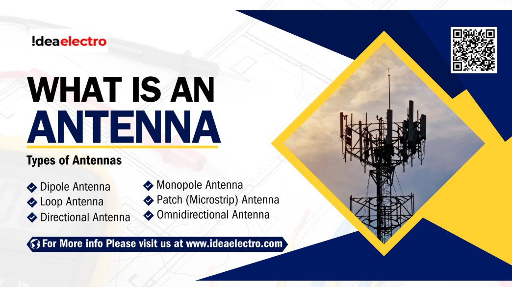
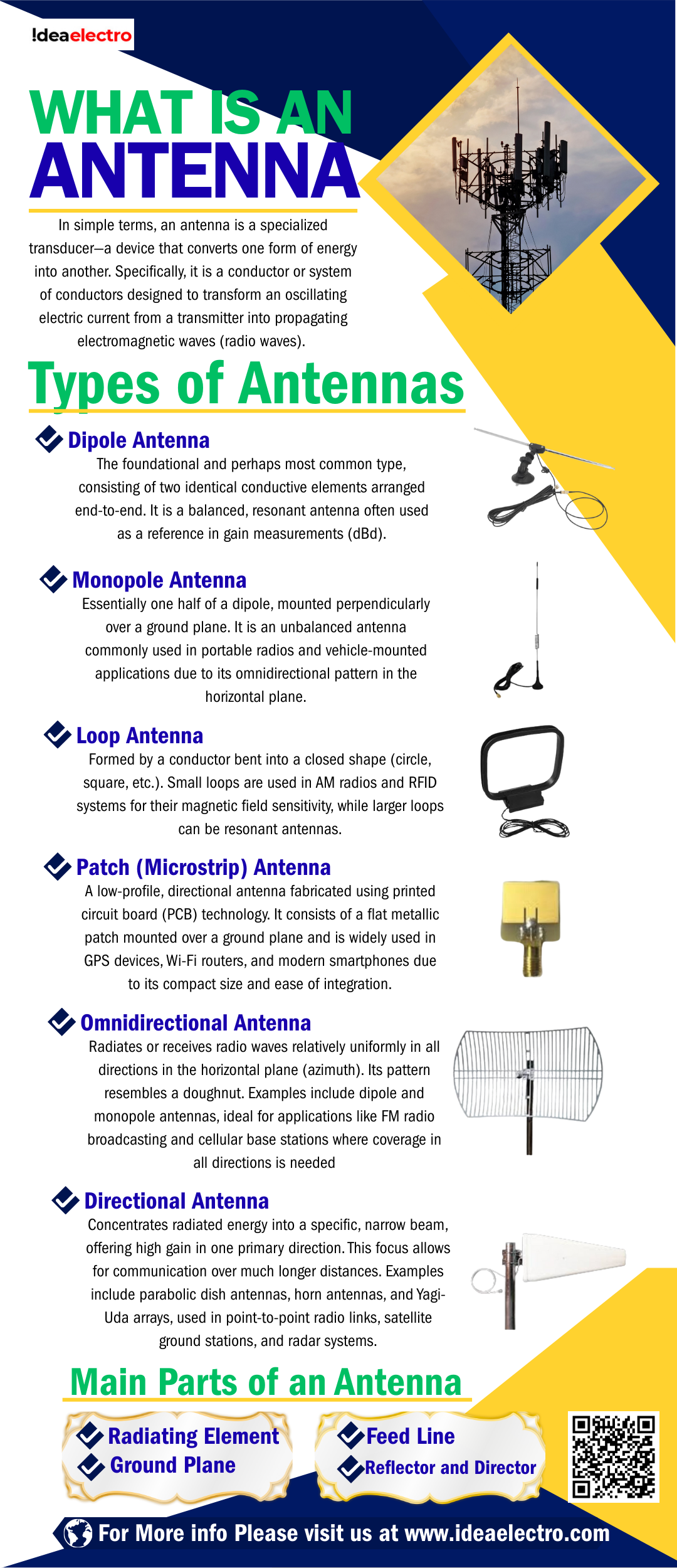
In simple terms, an antenna is a specialized transducer—a device that converts one form of energy into another. Specifically, it is a conductor or system of conductors designed to transform an oscillating electric current from a transmitter into propagating electromagnetic waves (radio waves). Conversely, when functioning in receive mode, it captures electromagnetic waves from free space and converts them back into an electric current that can be processed by a receiver. This dual functionality of transmission and reception is a core characteristic of most antennas. The physical form of an antenna can vary dramatically, from a simple straight piece of wire to a complex parabolic dish, but its fundamental purpose remains the same: to efficiently couple electrical energy from a circuit into radiating waves, or to extract energy from waves and deliver it to a circuit. This elegant process enables wireless communication over distances ranging from a few centimeters to millions of kilometers in space. These devices are embedded in a vast array of everyday technology, from the radios and televisions in our homes to the mobile phones in our pockets and the Wi-Fi routers that connect us to the internet. More sophisticated applications, such as satellite communications and global positioning systems (GPS), also rely entirely on specialized antenna technology. In essence, the modern electronic landscape is built upon the silent, invisible work of antennas, making them essential for telecommunications, broadcasting, navigation, and data networking.
How Does an Antenna Work?
The operation of an antenna is governed by the principles of electromagnetism. It functions as a resonant structure where the controlled movement of electrons creates and interacts with electromagnetic fields.
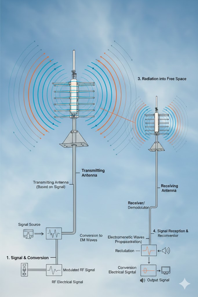
- Electrical Signal Generation and Conversion: For transmission, a radio frequency alternating current (AC) is applied to the antenna’s terminals via a feed line. This current causes free electrons within the metallic structure of the antenna to oscillate back and forth.
- Generation of Electromagnetic Waves: According to Maxwell’s equations, an accelerating electric charge produces a changing electric field, which in turn generates a changing magnetic field. These mutually reinforcing, oscillating fields detach from the antenna and propagate through space as a transverse electromagnetic wave—a radio wave. The frequency of the generated wave matches the frequency of the applied AC signal.
- Radiation into Free Space: The antenna is designed to guide this energy into space efficiently. Its geometry determines the pattern in which the energy is radiated—whether uniformly in all horizontal directions or focused into a narrow beam.
- Signal Reception and Reconversion: The process is reciprocal for reception. An incoming electromagnetic wave, with its oscillating electric field, impinges on the antenna’s conductors. This field exerts a force on the free electrons, causing them to move and thus inducing a tiny, matching alternating current at the antenna’s terminals. This current is then sent to the receiver for amplification and processing.
Main Parts of an Antenna
While designs vary, many antennas share common structural components that define their performance. A short introductory paragraph can set the stage: The efficiency and characteristics of an antenna are largely determined by its physical construction. Key elements work together to ensure effective signal radiation, impedance matching, and directional control.
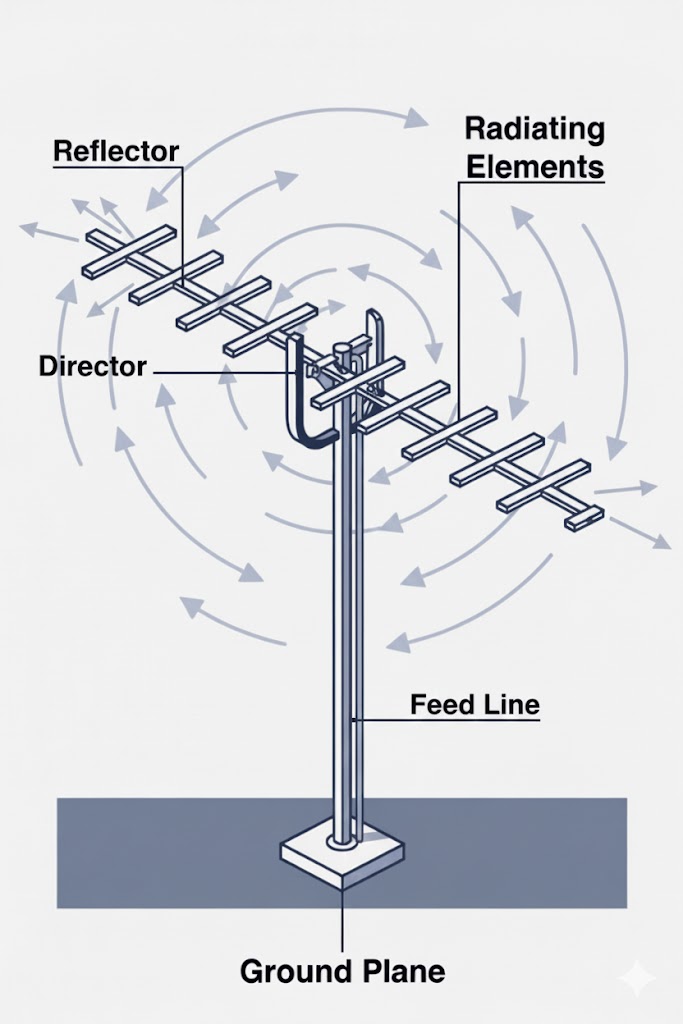
- Radiating Element: This is the primary conductive part (like a rod, wire, or patch) where current oscillates and electromagnetic waves are launched or captured. Its length is typically related to the wavelength of the desired operating frequency.
- Feed Line: This is the transmission cable (such as coaxial cable) that delivers the signal from the transmitter to the antenna’s feed point, or from the antenna to the receiver. It must efficiently transfer power with minimal loss.
- Ground Plane: A conductive surface or set of wires that acts as a reflective counterpart for the radiating element, particularly in monopole antennas. It creates an electrical image that influences the radiation pattern and is crucial for proper impedance matching.
- Reflector and Director: Found in directional antennas like the Yagi-Uda array, these are parasitic elements (not directly connected to the feed line) that re-radiate intercepted energy. A reflector placed behind the radiating element focuses energy forward, while directors placed in front further concentrate the beam, increasing gain and directivity.
Types of Antennas
Antennas are categorized based on their physical design and their radiation characteristics. The diversity in types exists to meet the specific requirements of different applications, such as frequency band, required coverage, and physical space constraints.
Based on Shape and Design
- Dipole Antenna: The foundational and perhaps most common type, consisting of two identical conductive elements arranged end-to-end. It is a balanced, resonant antenna often used as a reference in gain measurements (dBd).
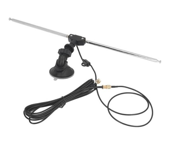
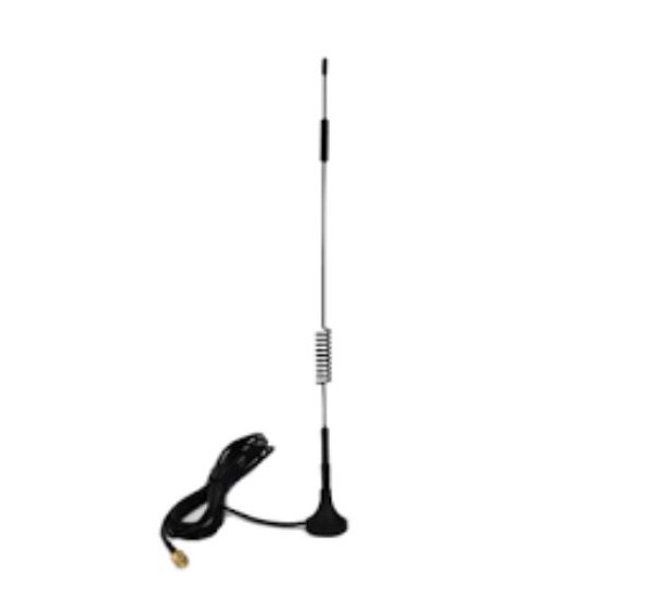
- Monopole Antenna: Essentially one half of a dipole, mounted perpendicularly over a ground plane. It is an unbalanced antenna commonly used in portable radios and vehicle-mounted applications due to its omnidirectional pattern in the horizontal plane.
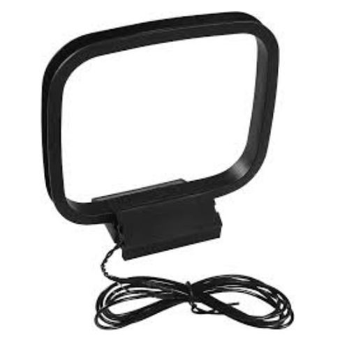
- Loop Antenna: Formed by a conductor bent into a closed shape (circle, square, etc.). Small loops are used in AM radios and RFID systems for their magnetic field sensitivity, while larger loops can be resonant antennas.
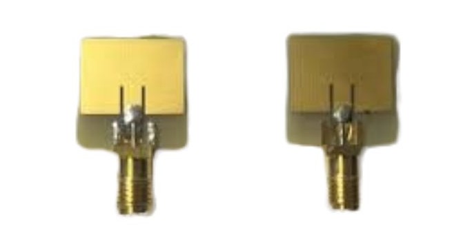
- Patch (Microstrip) Antenna: A low-profile, directional antenna fabricated using printed circuit board (PCB) technology. It consists of a flat metallic patch mounted over a ground plane and is widely used in GPS devices, Wi-Fi routers, and modern smartphones due to its compact size and ease of integration.
Based on Direction
- Omnidirectional Antenna: Radiates or receives radio waves relatively uniformly in all directions in the horizontal plane (azimuth). Its pattern resembles a doughnut. Examples include dipole and monopole antennas, ideal for applications like FM radio broadcasting and cellular base stations where coverage in all directions is needed.
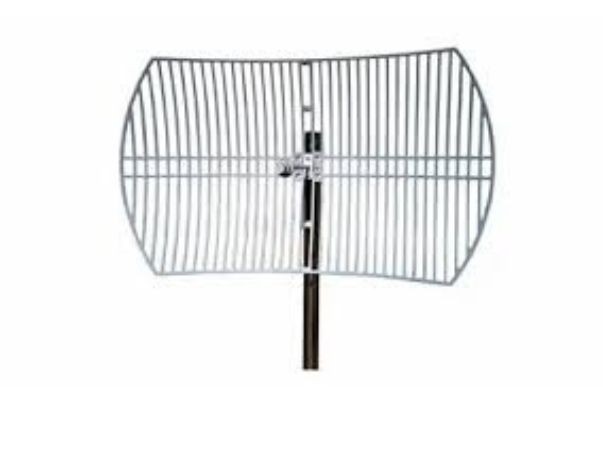
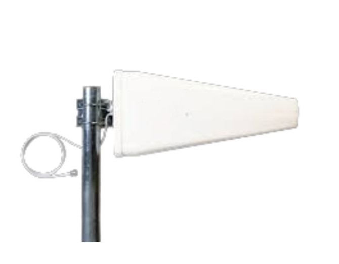
- Directional Antenna: Concentrates radiated energy into a specific, narrow beam, offering high gain in one primary direction. This focus allows for communication over much longer distances. Examples include parabolic dish antennas, horn antennas, and Yagi-Uda arrays, used in point-to-point radio links, satellite ground stations, and radar systems.
Common Antenna Parameters
To select the right antenna for a given application, engineers evaluate a set of standardized performance parameters. These specifications describe how an antenna will behave electrically and how it will interact with radio waves.
- Frequency Range & Bandwidth: The specific range of frequencies over which the antenna operates effectively. Bandwidth defines the width of this range and is often expressed as a percentage of the center frequency or in absolute units (MHz). An antenna’s bandwidth determines its ability to handle wideband signals or operate across multiple channels.
- Gain: A measure of how effectively an antenna focuses radiated power in a particular direction. It is expressed in decibels relative to an isotropic radiator (dBi) or a dipole (dBd). Higher gain indicates a more focused beam, which increases signal strength in the desired direction but reduces coverage in others.
- Radiation Pattern: A three-dimensional graphical representation of the distribution of radiated energy from the antenna. It shows lobes (areas of strong radiation) and nulls (areas of weak radiation), defining the antenna’s directivity and coverage.
- Polarization: The orientation of the electric field vector of the radiated wave. It can be linear (vertical or horizontal) or circular. For optimal power transfer, the polarization of the transmitting and receiving antennas should be matched.
- Impedance & VSWR: The input impedance (typically 50 or 75 ohms) must match the impedance of the connected feed line and transmitter to prevent signal reflections. The Voltage Standing Wave Ratio (VSWR) is a related metric that indicates the quality of this impedance match; a lower VSWR (closer to 1:1) signifies better efficiency.
Applications of Antennas
The applications of antennas are virtually limitless in the realm of wireless technology. They are the enabling hardware behind most forms of modern telecommunication.
- Mobile Phones and Cellular Networks: Handsets contain compact internal antennas (like patches or inverted-F antennas), while cell towers use arrays of sector antennas to provide omnidirectional or directional coverage.
- Radio and Television Broadcasting: High-power dipole arrays and towering mast radiators transmit AM/FM radio and TV signals over wide geographic areas to receivers with simple whip or dipole antennas.
- Wi-Fi and Bluetooth: Residential routers and IoT devices use integrated omnidirectional or patch antennas to provide local area network connectivity within homes and offices.
- Satellite Communication: Ground stations employ large, high-gain parabolic dishes to transmit narrow beams to satellites in orbit, which themselves are equipped with specialized antennas to cover specific footprints on Earth.
- GPS and Global Navigation: GPS receivers use small, circularly polarized patch antennas to pick up precise timing signals from a constellation of satellites.
- Radar Systems: Radar units utilize highly directional, often scanning, antennas (like parabolic dishes or phased arrays) to emit pulsed radio waves and detect their reflections from objects, enabling measurement of range, speed, and direction.
Advantages and Limitations of Antennas
Advantages
- Enables Wireless Communication: The primary advantage, eliminating the need for physical cables and enabling mobility for devices and users.
- Supports Long-Distance Links: Directional antennas can establish reliable communication over thousands of kilometers, connecting remote areas, ships at sea, and spacecraft.
- Facilitates Broadcast Services: A single transmitter with an appropriate antenna can serve an unlimited number of receivers within its coverage area, which is fundamental for radio, TV, and public alert systems.
Limitations
- Signal Interference and Propagation Issues: Wireless signals can be degraded by obstacles (buildings, hills), weather (rain fade for satellite links), and interference from other electronic devices operating on similar frequencies.
- Limited Range and Coverage Constraints: An antenna’s effective range is finite and governed by its power, gain, and the environment. Omnidirectional antennas trade range for broad coverage.
- Size and Placement Constraints: Efficient antennas at lower frequencies (like AM radio) must be physically large, which can be impractical. Placement is also critical, as nearby objects can severely distort an antenna’s radiation pattern.
Antenna vs. Cable Communication
The choice between wireless (antenna-based) and wired communication depends on the specific needs for mobility, installation ease, and signal integrity.
| Feature | Antenna (Wireless) | Cable (Wired) |
| Mobility | High – Devices can move freely within the coverage area. | Low – Devices are physically tethered to a fixed connection point. |
| Installation | Generally Easier – Requires no physical cabling to end-user devices; setup is faster for broad coverage. | More Complex – Requires extensive and precise installation of cables, conduits, and connectors. |
| Signal Loss & Stability | Possible and Variable – Signal strength decreases with distance and can be unstable due to interference and environmental factors. | Lower and More Stable – Cables (especially fiber optics) provide a shielded, predictable medium with very low loss and high immunity to interference. |
Conclusion
In summary, an antenna is a passive yet vital electronic component that acts as a bridge between guided electrical signals and free-space electromagnetic waves. Its ability to both transmit and receive by resonating at specific frequencies underpins all wireless technology. From the simple dipole to the complex phased array, the diversity in antenna design allows engineers to tailor solutions for everything from global satellite broadcasts to personal area networks. Understanding its core parameters—gain, bandwidth, polarization, and pattern—is key to harnessing its power effectively. Despite inherent limitations like signal propagation challenges, the antenna’s unparalleled advantage in providing untethered connectivity solidifies its role as a cornerstone of modern electrical engineering. It is this ingenious device that silently empowers our connected world, making instantaneous global communication a daily reality.