
Throughout my time working with electronics, few components have caused as much simultaneous relief and frustration as the relay. It is a deceptively simple device—essentially an electrically operated switch—yet it acts as the critical bridge between low-power control signals and high-power loads. When a system fails, the relay is often the first suspect, and rightly so.
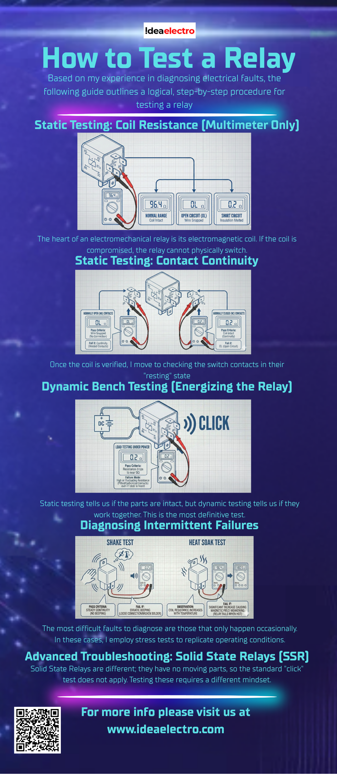
Based on my experience in diagnosing electrical faults, the following guide outlines a logical, step-by-step procedure for testing a relay. This approach prioritizes safety and accuracy, moving from visual checks to dynamic load testing.
Safety and Preparation
In my experience, the enthusiasm to find a fault often leads to skipping safety steps, which is where accidents happen. Before touching the component, I always enforce a strict safety protocol.
- Circuit De-energization: The first step is invariably verifying that the power source is completely disconnected. Removing a relay while a circuit is live can cause arcing, which damages the socket and poses a shock hazard.
- Capacitor Discharge: If the relay is part of a power supply or amplifier circuit, I ensure that any capacitors are fully discharged. Residual charge can linger long after the power is cut, presenting a silent danger.
- Tool Requirements: To perform these tests effectively, I prepare the following tools on my workbench:
- Digital Multimeter (DMM): Capable of measuring Resistance (Ohms) and Continuity.
- DC Power Supply or Battery: This must match the relay’s coil voltage (e.g., 12V for automotive relays).
- Jumper Wires: Alligator clips are essential for hands-free testing, allowing me to focus on the meter readings.
Preliminary Visual Inspection
Before connecting any diagnostic tools, I have found that a close visual examination often reveals the issue immediately.
- Physical Damage Check: I examine the casing for signs of thermal stress. Melting, hairline cracks, or the distinct smell of burnt plastic are clear indicators of a catastrophic failure.
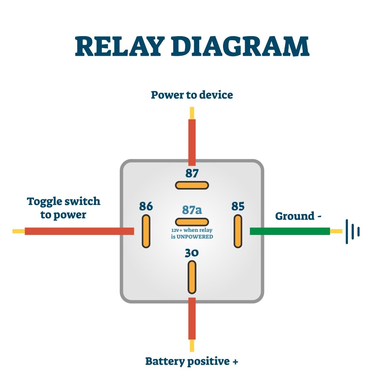
- Terminal Corrosion: I inspect the pins—specifically standard terminals like 30, 85, 86, and 87. Rust or oxidation creates high resistance, leading to intermittent operation. I also check for loose terminals that wiggle when touched.
- Diode Orientation: It is crucial to check the diagram printed on the relay to see if it contains a suppression diode. If overlooked, applying power with reverse polarity during testing will destroy this diode instantly.
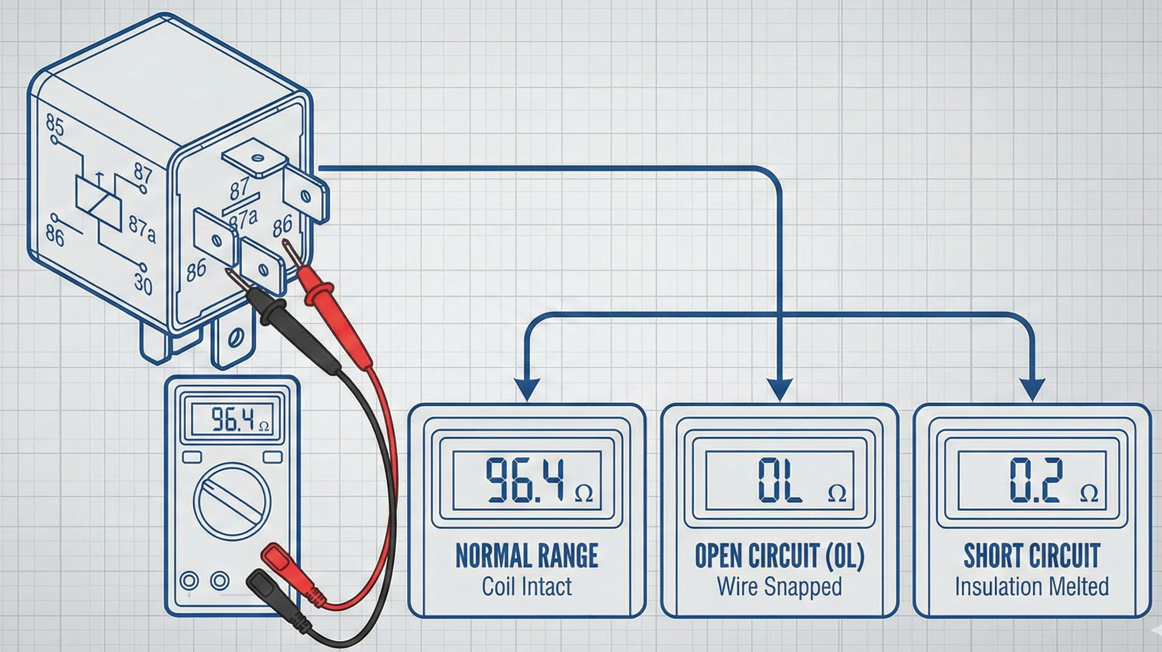
Static Testing: Coil Resistance (Multimeter Only)
The heart of an electromechanical relay is its electromagnetic coil. If the coil is compromised, the relay cannot physically switch.
- Identifying Coil Pins: On a standard automotive or DIN relay, these are pins 85 and 86. However, I always double-check the datasheet or the schematic printed on the side of the casing.
- Measuring Resistance: With the multimeter set to Ohms mode, I measure across these two pins.
- Interpreting Values:
- Normal Range: I typically look for a reading between 50Ω and 150Ω. This confirms the copper winding is intact.
- Open Circuit (OL): If the meter reads “OL” (Open Loop), the internal wire has snapped. The relay is dead and requires replacement.
- Short Circuit (Near 0Ω): A reading near zero suggests the insulation between the wire turns has melted, creating a short. This is dangerous as it can damage the control circuit that drives the relay.
Static Testing: Contact Continuity
Once the coil is verified, I move to checking the switch contacts in their “resting” state.
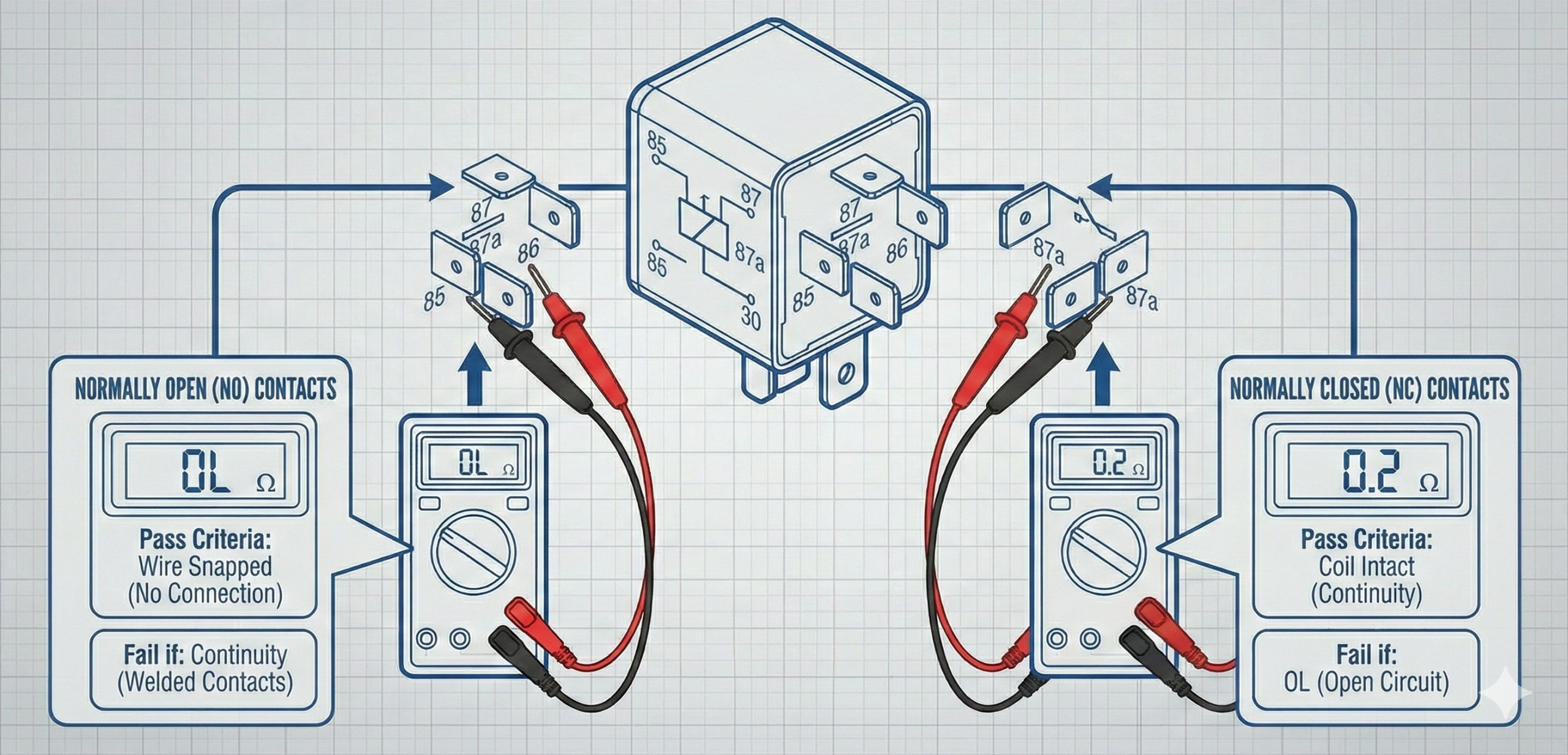
- Normally Open (NO) Contacts:
- I connect the probes to the Common pin (30) and the Normally Open pin (87).
- Pass Criteria: Since the relay is not energized, there should be no connection. The meter must read “OL” or infinite resistance. If there is continuity here, the contacts have likely welded together due to high current arcing.
- Normally Closed (NC) Contacts:
- If the relay has a fifth pin (87a), I measure between Common (30) and NC (87a).
- Pass Criteria: This should show continuity (near 0Ω or a beep).
Dynamic Bench Testing (Energizing the Relay)
Static testing tells us if the parts are intact, but dynamic testing tells us if they work together. This is the most definitive test.
- Setup: I connect the power supply to the coil pins (85 and 86) using jumper wires.
- Auditory Test: When power is applied, I listen for a distinct, sharp “click.” This sound confirms the armature is mechanically moving.
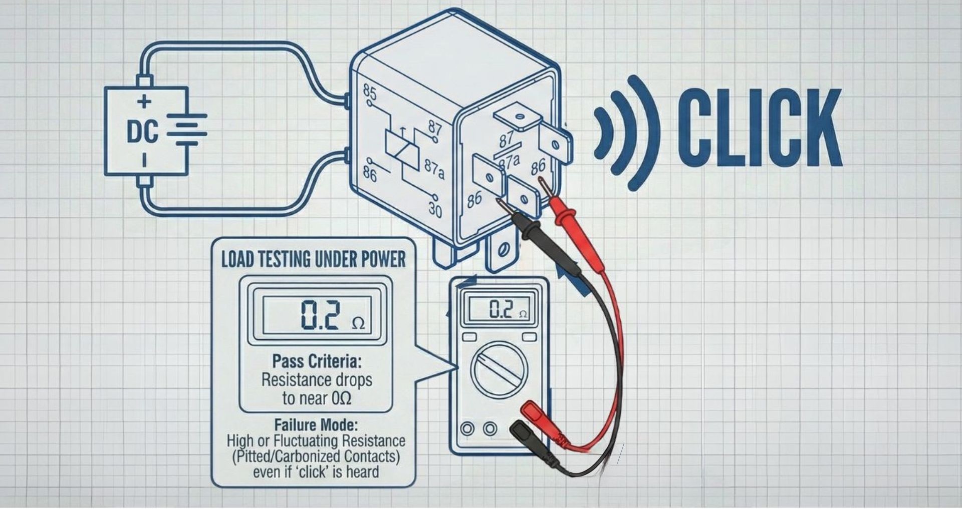
- Load Testing Under Power:
- While the coil is energized (clicking), I measure the resistance across the switched pins: Common (30) and NO (87).
- Pass Criteria: The resistance must drop from Infinite to near 0Ω.
- Failure Mode: I have encountered many relays that “click” but still fail. If the relay clicks but the resistance remains high (or fluctuates), the internal contacts are pitted or carbonized. The mechanism moves, but it cannot conduct electricity effectively.
Advanced Troubleshooting: Solid State Relays (SSR)
Solid State Relays are different; they have no moving parts, so the standard “click” test does not apply. Testing these requires a different mindset.
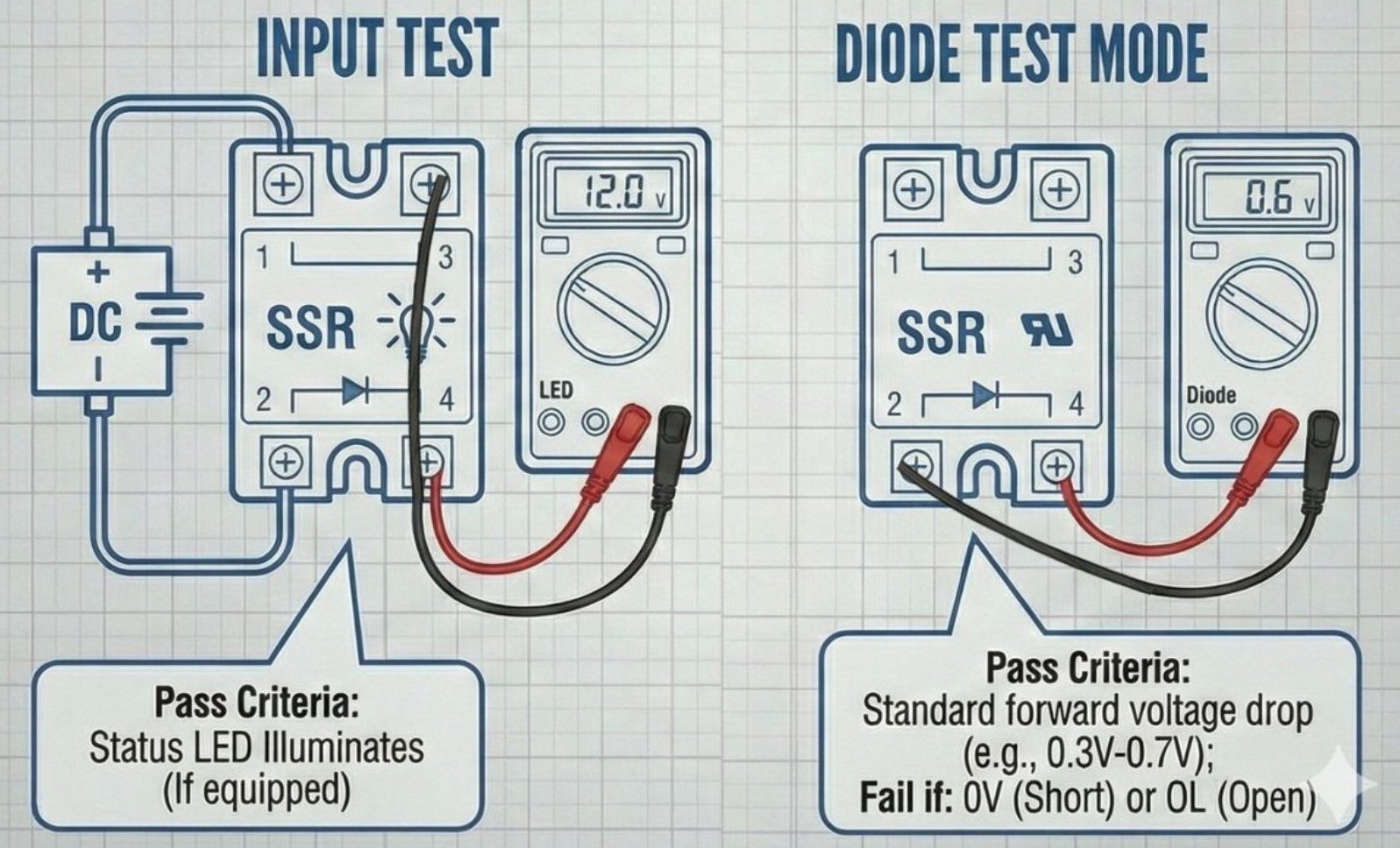
- Input Test: I apply the control voltage and check if the internal status LED illuminates (if equipped).
- Output Leakage Test: A common failure mode in SSRs is “failing closed.” I measure the load side when the input is OFF. Significant current leakage indicates the internal semiconductor has shorted.
- Diode Test Mode: Since there is no physical switch, I use the multimeter’s Diode mode to check the output terminals for semiconductor health, looking for standard forward voltage drops rather than simple continuity.
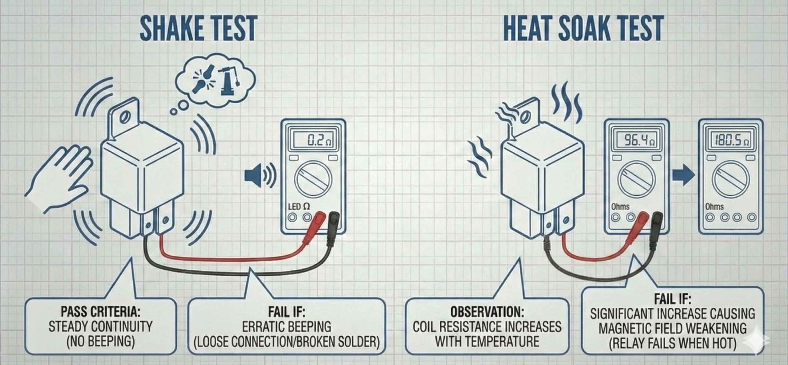
Diagnosing Intermittent Failures
The most difficult faults to diagnose are those that only happen occasionally. In these cases, I employ stress tests to replicate operating conditions.
- Shake Test: While measuring continuity, I gently shake or tap the relay. If the meter beeps erratically, it indicates a loose internal armature or a broken solder joint inside the casing.
- Heat Soak: I have observed that coil resistance increases with temperature. A relay might work on a cold bench but fail in a hot engine bay. Heating the relay slightly (using a heat gun on low or simply re-testing after it has been active) can reveal thermal failures where the magnetic field becomes too weak to pull the switch.