In the field of electronics repair and engineering, few components demand as much respect as the capacitor. Through my years of diagnosing power supplies and vintage amplifiers, I have learned that a capacitor is effectively a temporary battery that does not care if the device is unplugged. It stands ready to release its stored energy instantaneously.
The following guide details the logical, safe procedures for discharging capacitors, drawing upon standard safety protocols and professional experience.
Safety First: The Critical Pre-Step
Before even opening a chassis, one must acknowledge the risk. Capacitors store energy in an electric field. Unlike a resistor or a diode, a capacitor can deliver a lethal electric shock even days after the device has been disconnected from its power source.
Personal Protective Equipment (PPE) In my practice, I never approach high-voltage electronics (such as tube amplifiers or microwave ovens) without proper PPE.
- Insulated Gloves: Essential for preventing current form passing through the hands.
- Safety Goggles: Capacitors can fail explosively if shorted incorrectly; eye protection is mandatory.
Disconnect Power The device must be completely isolated. Unplug the unit from the wall outlet and remove any batteries. Do not rely on the power switch alone, as it may only break the live wire while leaving neutral connected, or the capacitor may be physically located before the switch in the circuit.
Note: Before handling, it is crucial to understand how a capacitor works to appreciate why it retains a lethal charge. The dielectric material inside holds energy regardless of external power status.
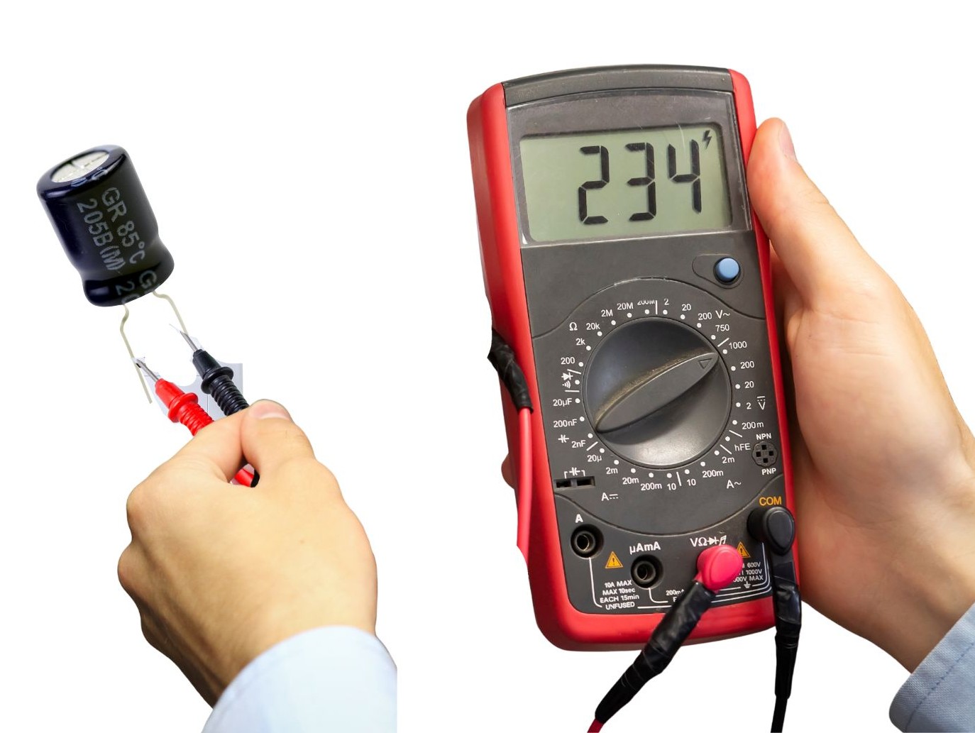
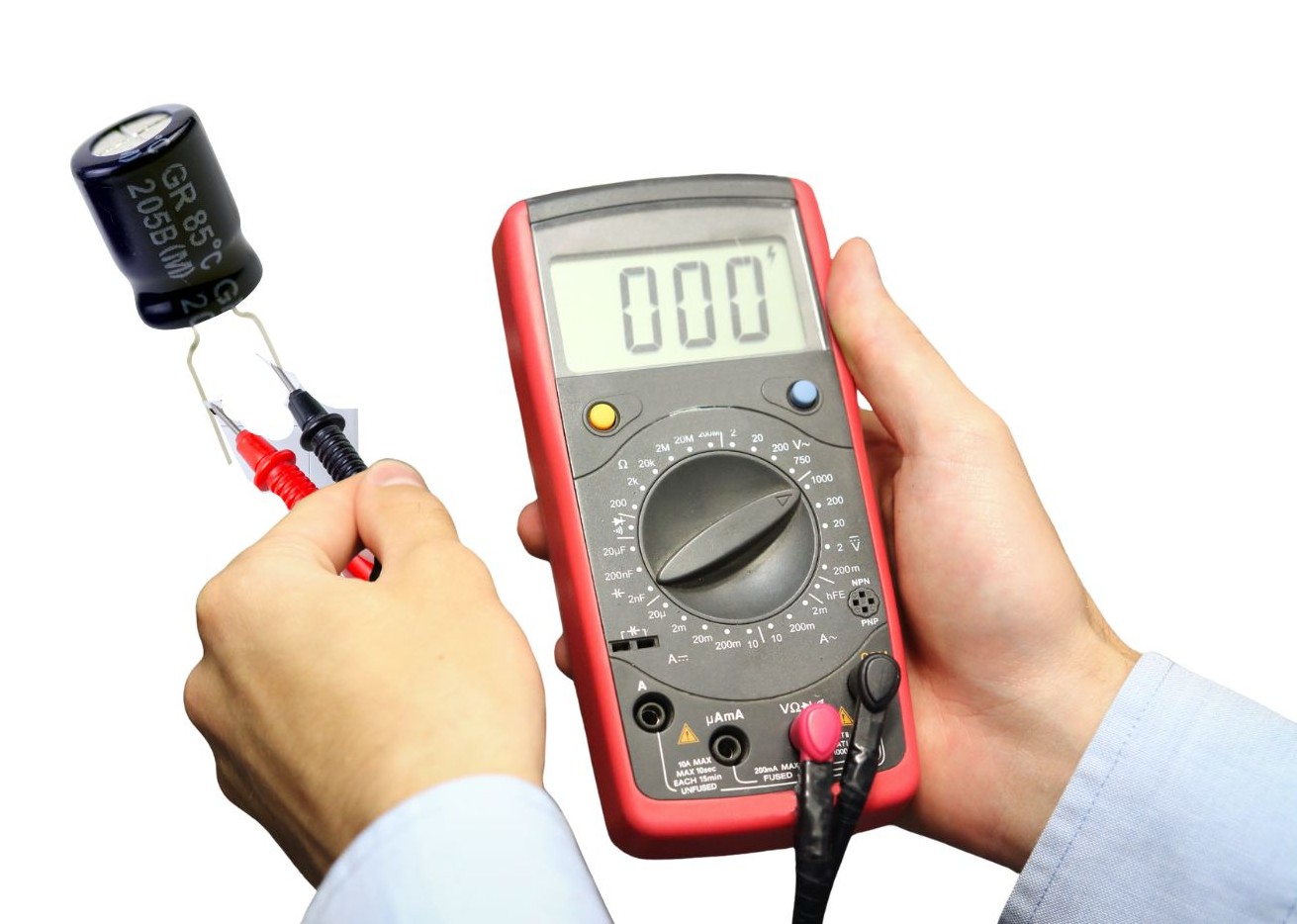
Verifying the Charge (Initial Check)
One should never assume a capacitor is charged or discharged based on guesswork. I always verify the state of the component before selecting a discharge method.
Multimeter Setup
- Set your digital multimeter to DC Voltage (VDC) mode. Ensure the range is higher than the capacitor’s rated voltage.
- Carefully probe the capacitor terminals.
Why Verification Matters I have encountered situations where “bleeder resistors” (components designed to drain the capacitor automatically) had failed. Had I assumed the circuit was safe because it had been off for an hour, I would have been exposed to high voltage. The multimeter confirms the actual presence of danger.
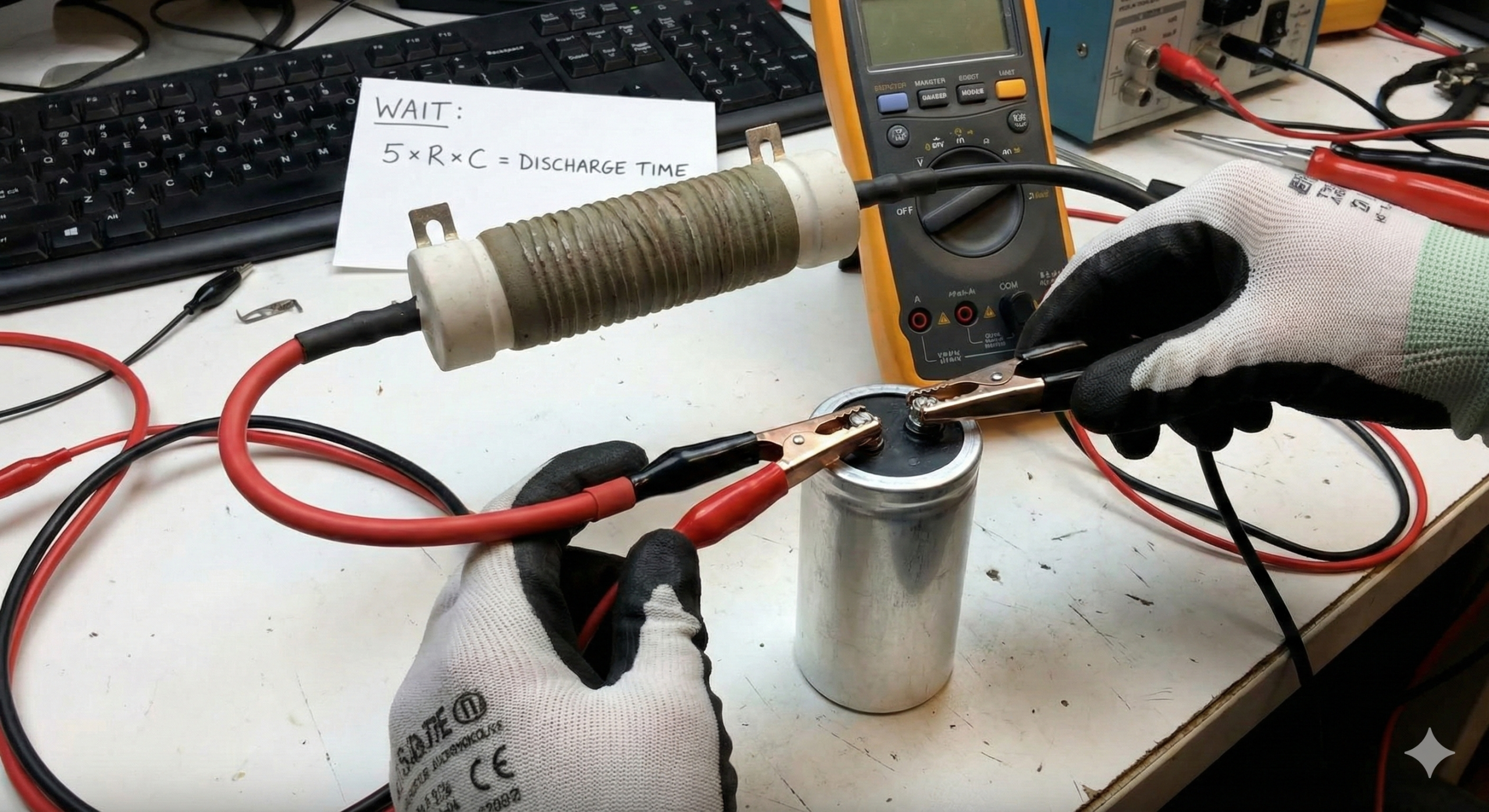
Method 1: The Resistor Method (Safest & Recommended)
This is the industry-standard method and the one I use for 90% of my work. It involves using a resistor to bridge the capacitor terminals.
Concept Instead of creating a chaotic short circuit, the resistor limits the current, allowing the energy to bleed off as heat in a controlled manner. This prevents sparks and protects the capacitor’s internal structure.
Choosing the Right Resistor
- High Voltage: For large power supply caps, I recommend a 20kΩ 5W resistor (wire-wound).
- Low Voltage: For smaller logic boards, a 1kΩ resistor is usually sufficient.
Note: The discharge rate is determined by the time constant (RC), which you can learn more about in our foundational guide.
The Procedure
- Preparation: I utilize a custom tool I built: a high-wattage resistor with insulated wires and alligator clips soldered to each end.
- Connection: Clip one end to the negative terminal and Touch or clip the other end to the positive terminal.
- Wait: Allow time for the discharge. A good rule of thumb is to wait for 5-time constants (5 x Resistance x Capacitance) to ensure the voltage is effectively zero.
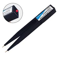
Method 2: The Discharge Tool (Professional Approach)
For those performing frequent repairs, commercial discharge tools are highly effective. These are often shaped like pens or wands.
Visual Confirmation These tools typically contain an internal resistance circuit coupled with an LED or neon lamp. As you touch the probes to the capacitor, the light glows brightly. As the voltage drops, the light fades.
Pros/Cons From my experience, the visual feedback provides excellent peace of mind. You can physically see the energy leaving the system. However, for a hobbyist doing a one-off repair, purchasing a specific tool may be an unnecessary expense compared to the resistor method.
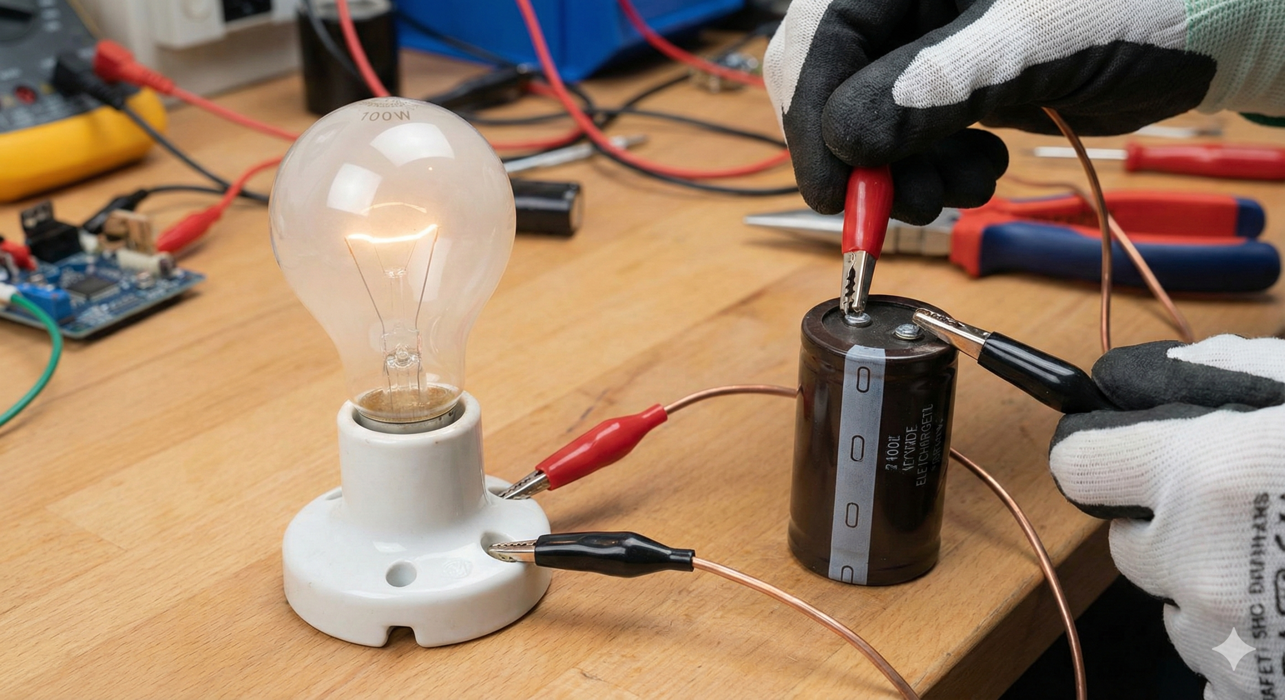
Method 3: The Light Bulb Method (Visual DIY)
This is a method I often used early in my career for mains-voltage capacitors.
Setup Mount a standard incandescent light bulb (e.g., 100W for mains capacitors) into a socket equipped with two insulated wire leads.
Execution Touch the leads to the capacitor terminals.
Benefit Similar to the professional tool, the bulb lights up instantly and then dims as the capacitor discharges. This provides a clear visual indication that the energy is leaving the dielectric material. It acts as both a load (resistor) and an indicator.
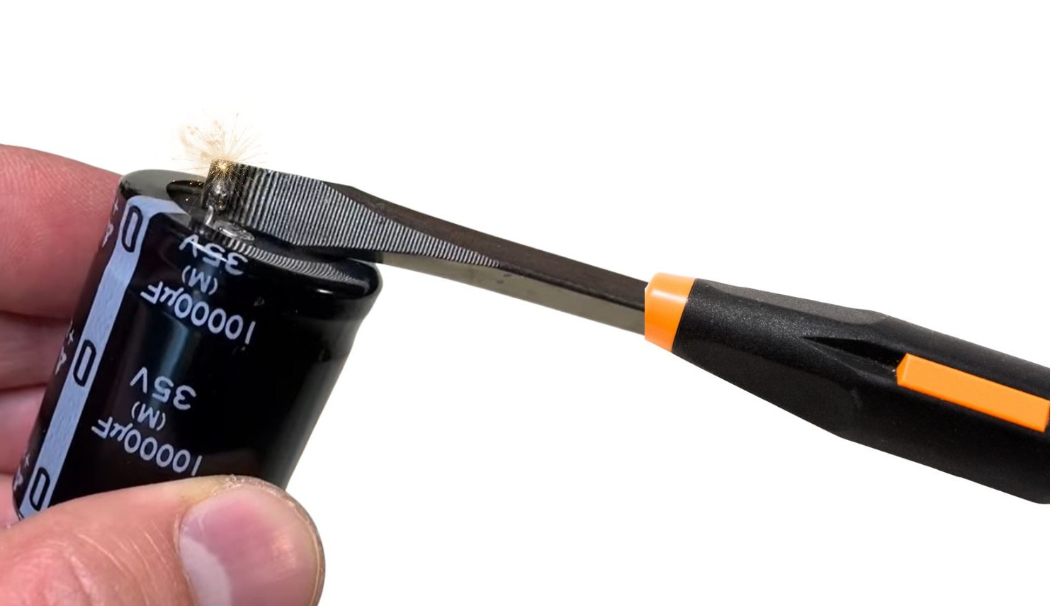
Method 4: The Screwdriver Method (The “Spark” Method)
Disclaimer: This method is NOT Recommended for beginners, high-voltage electronics, or sensitive printed circuit boards (PCBs).
When It’s Used I only utilize this method in emergency situations involving very small, low-voltage capacitors where I am certain the energy release will be negligible.
Precautions Using a screwdriver with a heavy, insulated handle, one bridges the two terminals.
Personal Experience Warning I strongly advise against this for high-voltage capacitors. Early in my training, I witnessed a technician short a large power supply capacitor with a screwdriver. The resulting arc flash welded the screwdriver tip to the terminal and damaged the PCB traces. It creates a massive current spike that can internally damage the capacitor and is startlingly loud.
Final Verification and Post-Discharge Safety
The process is not complete until the meter reads zero.
The “Zero Volts” Check Return to the multimeter setup used in Step 2. Probe the terminals again to ensure the reading is 0V.
Shorting the Terminals Once the meter reads zero, I briefly short the terminals with a wire.
Note: Certain types, like Electrolytic Capacitors, are prone to retaining residual charge even after a quick discharge.
This phenomenon is known as dielectric absorption or “recovery voltage,” where charge “hiding” in the dielectric migrates back to the plates. A final short ensures the component is truly dead.
Conclusion
While the temptation to create a spark with a screwdriver exists, the Resistor Method remains the superior choice for the longevity of your tools, the safety of the circuit, and your personal well-being. Electronics repair requires patience; taking the extra minute to construct a resistor discharge tool is an investment in safety that every technician should make.