

The Ground Plane (GP) antenna stands as one of the most recognizable and widely utilized omnidirectional antennas in the field of radio frequency (RF) engineering. Defined by its central vertical radiator and a set of horizontal or angled radials, it is favored for its remarkable simplicity and ease of construction. These characteristics make it a go-to choice for Very High Frequency (VHF) and Ultra High Frequency (UHF) applications, where its compact size and efficiency are highly valued. According to the American Radio Relay League (ARRL), the ground plane antenna is a fundamental design that serves as the basis for many more complex vertical antenna systems.
At its core, the primary function of the Ground Plane antenna is to facilitate long-distance, line-of-sight communication by producing a low-angle radiation pattern. By concentrating energy toward the horizon rather than wasting it by radiating into space, the GP antenna ensures that signals remain close to the earth’s surface, which is ideal for ground-to-ground or ground-to-mobile communications. Research into antenna patterns indicates that this low-angle radiation is a key factor in maximizing the range of terrestrial radio systems.
The Core Components
The physical structure of a Ground Plane antenna is straightforward, consisting of two primary elements: The Driven Element and the Radials. The Driven Element is the vertical component that actually radiates the RF energy, typically cut to a length of $1/4$ wavelength of the operating frequency. The radials, which extend outward from the base, create an “artificial ground” that allows the antenna to function efficiently even when mounted high above the literal earth. The point where these components meet is known as the feed point, where the coaxial cable from the transmitter is connected. Scientific analysis of antenna impedance suggests that the relationship between these parts determines the overall efficiency of the system.
| Component | Function | Orientation |
| Driven Element | Radiates the signal; $1/4$ wavelength long. | Vertical |
| Radials | Acts as the “artificial ground” for RF current. | Horizontal or Slanted |
| Feed Point | Where the coaxial cable connects to the system. | Base of Vertical |
How It Works: Creating the “Mirror”
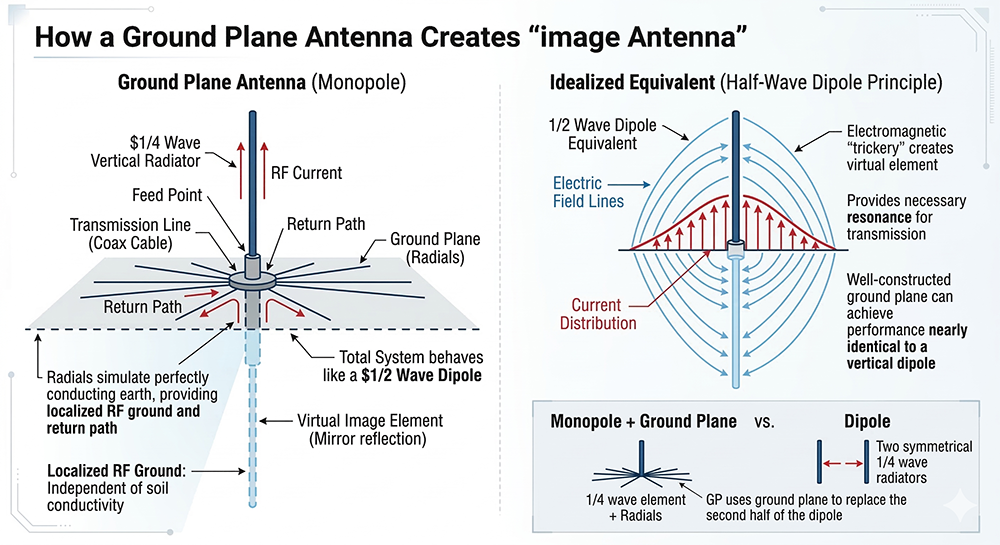
The operation of a Ground Plane antenna relies on the fascinating concept of the Image Antenna. Because a $1/4$ wave vertical is technically only half of a resonant system, it requires a reflective surface to complete its electrical circuit. The radials simulate a perfectly conducting earth, allowing the vertical element to “see” its own reflection. This electromagnetic trickery makes the $1/4$ wave vertical behave like a $1/2$ wave dipole, providing the resonance necessary for transmission. NASA’s technical documentation on antenna systems highlights how the ground plane serves as a mirror to create this virtual image element.
- RF Grounding: In many installations, such as those on rooftops or wooden masts, a direct connection to the physical earth is impractical. Radials provide a localized RF ground that is independent of soil conductivity.
- Current Distribution: The radials provide a low-impedance return path for the RF current. This is essential for maintaining the balance of the system and preventing “RF in the shack,” where signals travel back down the outside of the cable.
- Monopole vs. Dipole: While a dipole uses two symmetrical $1/4$ wave radiators, the GP antenna is a “monopole” that uses the ground plane to replace the second half of the dipole. Studies show that a well-constructed ground plane can achieve performance nearly identical to a vertical dipole.
Radiation Pattern and Polarization
Ground Plane antennas are inherently omnidirectional, meaning they radiate energy equally in a 360-degree circle around the vertical element. This makes them perfect for “base station” applications where the user needs to communicate with mobile units moving in any direction. Furthermore, because the driven element is oriented vertically, the signal is Vertically Polarized. This matches the orientation of most mobile and handheld whip antennas, reducing signal loss caused by polarization mismatch.
The radiation angle is another critical factor; the GP antenna focuses its energy at a low angle toward the horizon. This is vital for maintaining a strong “line-of-sight” connection over long distances or when communicating with satellites at low elevations. Research by the IEEE on propagation confirms that low-angle radiation is superior for minimizing atmospheric interference in VHF/UHF bands.
The Importance of Radial Angle
The angle at which the radials are mounted significantly impacts the antenna’s electrical characteristics, specifically its impedance.
- Horizontal Radials (90°): When radials are perfectly horizontal, the antenna typically exhibits an impedance of approximately $36\Omega$. Since most modern transmitters and coaxial cables are designed for $50\Omega$, this creates a mismatch that can lead to a high Standing Wave Ratio (SWR), reducing efficiency.
- Drooping Radials (45°): By bending the radials downward at roughly a 45-degree angle, the radiation resistance increases toward $50\Omega$. This provides a much better match for standard coax, allowing for maximum power transfer without the need for complex tuning circuits.
- Mounting Height: Elevating the antenna away from the physical ground reduces the capacitive coupling with the earth, which helps maintain the intended low-angle radiation pattern and stabilizes the SWR. Engineering data suggests that elevating a GP antenna by at least $1/2$ wavelength significantly improves its performance.
Applications in Modern Communication
Despite being an older design, the Ground Plane antenna remains a staple in modern telecommunications due to its reliability.
- Amateur Radio (Ham): It is a favorite for DIY enthusiasts building antennas for the 2-meter ($144$ MHz) or 70-cm ($440$ MHz) bands.
- Aviation: Most airports utilize ground plane variants for VHF ground-to-air communications, ensuring clear audio for air traffic control.
- Emergency Services: Police, fire, and EMS dispatch centers often use high-gain vertical antennas based on ground plane principles for their fixed base stations.
- Marine: Shore-based VHF stations use these antennas to provide reliable coverage for ships at sea, where vertical polarization is the standard for marine safety.
Advantages and Disadvantages
| Pros | Cons |
| Simple and cost-effective to construct from basic materials. | Requires a significant footprint for the radial wires. |
| Does not require a massive tower; can be mounted on a simple mast. | The horizontal radials can create high wind loading in storms. |
| Provides the low radiation angle necessary for distance. | Limited to vertical polarization, which may not suit all needs. |
 Conclusion: The Versatile Vertical
The Ground Plane antenna remains a cornerstone of RF technology because it balances simplicity with high performance. Its ability to create a “virtual” ground makes it incredibly versatile for various environments, from backyard hobbyist setups to critical aviation infrastructure. For any student or professional in the field of electrical engineering, mastering the ground plane is the first step toward understanding the complex world of wave propagation.