During my early years working with electrical circuits, I recall the distinct, hum of a large transformer in a university laboratory. It was a massive, oil-cooled unit, motionless yet vibrating with energy. To the uninitiated, it looked like a simple metal box, but to those of us studying the flow of power, it represented a fundamental principle of modern engineering: the ability to trade current for voltage.
This device was a step-up transformer. Its function is not merely to change numbers on a multimeter, but to make the transmission of electricity over vast distances physically and economically possible. Below, I will detail the mechanics, design, and critical importance of the step-up transformer, drawing on logical principles and practical observations.
![]()
Defining the Step-Up Mechanism
At its heart, a transformer is a device of conservation. It does not create power; it transforms it. In my experience, understanding the step-up transformer requires visualizing it as a lever for electricity—trading distance (current) for force (voltage).
The Core Function
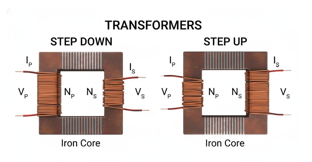
The primary definition of a step-up transformer is a device where the output voltage ($V_s$) is greater than the input voltage ($V_p$). It takes a lower voltage source—such as the output from a power generator—and boosts it to a higher level suitable for transmission or specific high-voltage machinery.
The Turns Ratio Rule
This boosting capability is dictated by the physical construction of the coils, specifically the “turns ratio.” During coil winding experiments, one quickly learns the golden rule: to step up voltage, the secondary coil (output) must have more turns of wire than the primary coil (input).
Mathematically, this relationship is expressed as:
$$N_s > N_p$$
Where $N_s$ is the number of turns on the secondary side and $N_p$ is the number of turns on the primary side. If you double the turns on the secondary side, you effectively double the voltage.
Current vs. Voltage Inverse
There is a common misconception that stepping up voltage increases the total power. In practice, nature demands a trade-off. To satisfy the Law of Conservation of Energy (assuming an ideal transformer where Power Input $\approx$ Power Output), an increase in voltage must result in a proportional decrease in current.
$$P_{in} \approx P_{out} \implies V_p I_p \approx V_s I_s$$
When we step up the voltage, we inevitably step down the current. This “inverse” relationship is the key to the transformer’s utility in power transmission.
Design & Construction Specifics
When you disassemble a transformer (a task I have performed on smaller failed units to understand their failure points), the difference between the primary and secondary sides is visually striking. They are not mirror images; they are specialized for their specific electrical burdens.
Winding Gauge Differences
- Primary (Input): On a step-up transformer, the input side handles lower voltage but significantly higher current. Consequently, the copper wire used here is thick and heavy. In hand-wound prototypes, bending this wire requires significant physical effort because it must be thick enough to minimize resistance and prevent overheating under high current loads.
- Secondary (Output): conversely, the secondary side handles high voltage but very low current. The wire here is much finer, sometimes as thin as a hair in small electronics. Because the current is low, the copper cross-section does not need to be large.
Insulation Challenges
While the wire on the secondary side is thinner, the insulation requirements are far stricter. I have seen transformers fail due to “arcing”—where electricity jumps across the insulation due to extreme voltage pressure. Because the secondary side operates at high voltage, the enamel coating on the wire and the insulating paper between layers must be robust to prevent short circuits.
Rating Considerations
Transformers are rated in kVA (kilovolt-amperes), not just watts. This is because the insulation and the wire thickness are physical limits. A step-up transformer must be designed to withstand the heat generated by the current (on the primary) and the dielectric stress generated by the voltage (on the secondary).
The “Why” of Stepping Up: Transmission Efficiency
Why go through the trouble of boosting voltage to dangerous levels, only to step it back down later? The answer lies in the physics of resistance.
Combatting $I^2R$ Losses
When electricity flows through a wire, energy is lost as heat. This loss is calculated by the formula $P_{loss} = I^2R$.
The crucial variable here is current ($I$), which is squared. If you double the current, you quadruple the losses.
By using a step-up transformer, engineers reduce the current significantly while maintaining the same power transfer. By lowering the current, we drastically reduce the energy wasted as heat during transmission. This is not just a theoretical improvement; it is the only way to send power hundreds of miles without losing most of it along the way.
The Grid Ecosystem
At power plants, you will find the “Generator Step Up” (GSU) transformer. Generators typically produce electricity at medium voltages (e.g., 12kV to 25kV). However, the transmission grid operates at massive voltages (e.g., 230kV or 400kV). The GSU acts as the bridge, boosting the voltage immediately so it can enter the grid efficiently.
Key Applications Beyond the Grid
While the power grid is the most prominent example, my experience in electronics repair has highlighted the ubiquity of step-up transformers in smaller devices.
- Industrial Equipment: Devices like microwave ovens and X-ray machines require thousands of volts to operate the magnetron or X-ray tube. Inside a microwave, a heavy step-up transformer converts your standard household 120V/230V into the roughly 2000V required for the system.
- Power Electronics: In Uninterruptible Power Supplies (UPS) and inverters, a battery provides low DC voltage (e.g., 12V). To run household appliances, this must be converted and stepped up to standard AC mains voltage.
- Electric Motors: Some induction motors require a higher starting voltage to overcome initial inertia. Auto-transformers (a variation of the step-up) are often used to provide this temporary boost.
Advantages & Limitations
Shutterstock
Reflecting on the operational realities of these devices, the benefits clearly outweigh the drawbacks, though the risks must be managed.
Pros
- Long-Distance Transfer: Without stepping up voltage, power plants would need to be located every few miles.
- Cost Reduction: Because high voltage allows for low current, transmission lines can use thinner, lighter, and less expensive cables.
Cons
- Cooling Requirements: Despite high efficiency, large transformers still generate heat. They require complex cooling systems, such as oil baths or radiator fans.
- Safety Risks: Working with stepped-up voltage introduces lethal hazards. The insulation systems must be massive and expensive to contain the potential for arcing.
Summary: The Backbone of High-Voltage Distribution
The step-up transformer is a silent workhorse. It is a device defined by a simple trade: giving up current to gain voltage. By utilizing the turns ratio rule ($N_s > N_p$) and thick primary windings, it allows us to overcome the limitations of resistance ($I^2R$ losses). Whether in the hum of a microwave or the towering substations of the national grid, the step-up transformer is the essential link that allows electrical energy to travel from where it is made to where it is needed.