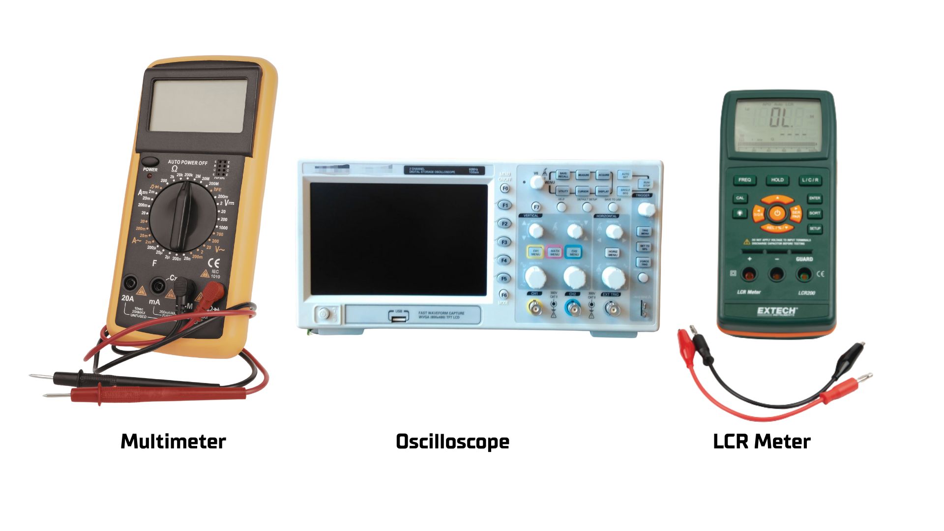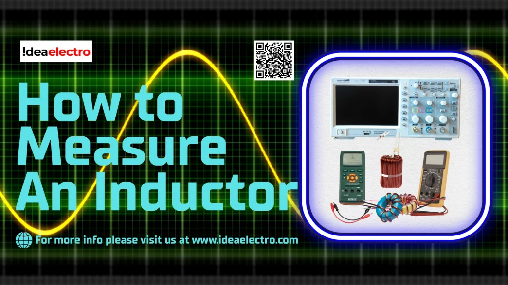
Why Standard Multimeters Are Often Insufficient
For many electronics enthusiasts, the digital multimeter is the primary diagnostic tool. However, when working with inductors (coils), a standard multimeter often provides an incomplete picture.
- The DC Limitation: Standard multimeters operate using Direct Current (DC). To a DC signal, an ideal inductor is simply a length of conductive wire. Consequently, the multimeter measures the Direct Current Resistance (DCR)—the physical resistance of the copper wire—rather than the inductance. Inductance is the property that opposes changes in current, a behavior that only manifests when Alternating Current (AC) or changing signals are applied.
- Continuity Testing: Despite this limitation, a multimeter is valuable for initial “triage.” It can confirm continuity. A reading of infinite resistance indicates an open circuit (a broken wire), while a reading of near-zero resistance confirms the wire is intact. However, this does not reveal if the coil has internal shorted turns or if it will function correctly as an energy storage device.
- Resistance vs. Impedance: It is vital to distinguish between physical resistance (measured in Ohms, static) and impedance (the total opposition to current flow in an AC circuit). An inductor’s opposition to current, known as inductive reactance, rises as the frequency of the signal increases. To truly measure an inductor, one must measure its behavior under AC conditions, not just its wire resistance.
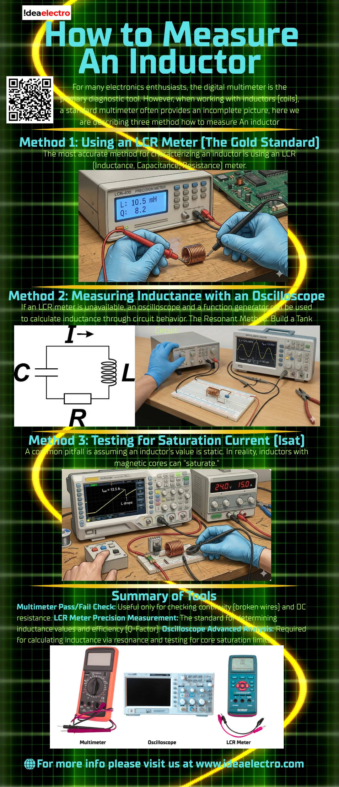
Method 1: Using an LCR Meter (The Gold Standard)
The most accurate method for characterizing an inductor is using an LCR (Inductance, Capacitance, Resistance) meter.
- Device Setup: Selecting the correct test frequency is critical. Inductors behave differently depending on the frequency of the current passing through them.
- Power Inductors: Large iron-core coils used in power supplies are typically tested at lower frequencies (e.g., 100Hz or 120Hz).
- RF Coils: Small air-core coils used in radio applications should be tested at higher frequencies (e.g., 100kHz or 1MHz) to simulate real-world operating conditions.
- Calibration: To ensure accuracy, “Open” and “Short” compensation must be performed before testing.
- Open: Calibrating with leads separated removes stray capacitance.
- Short: Calibrating with leads connected removes the resistance and inductance of the test leads themselves.
- Selecting the Circuit Mode:
- Series Mode (Ls): Best for low-impedance inductors (typically those below 10kΩ). This model assumes series resistance is the dominant source of error.
- Parallel Mode (Lp): Best for high-impedance coils. This model accounts for parallel losses, such as core loss or inter-winding capacitance.
- Interpreting the Readout: The primary display indicates the Inductance ($L$). The secondary display often shows the Q-Factor (Quality Factor). A high Q-Factor suggests a high-quality inductor that stores energy efficiently with minimal energy loss.
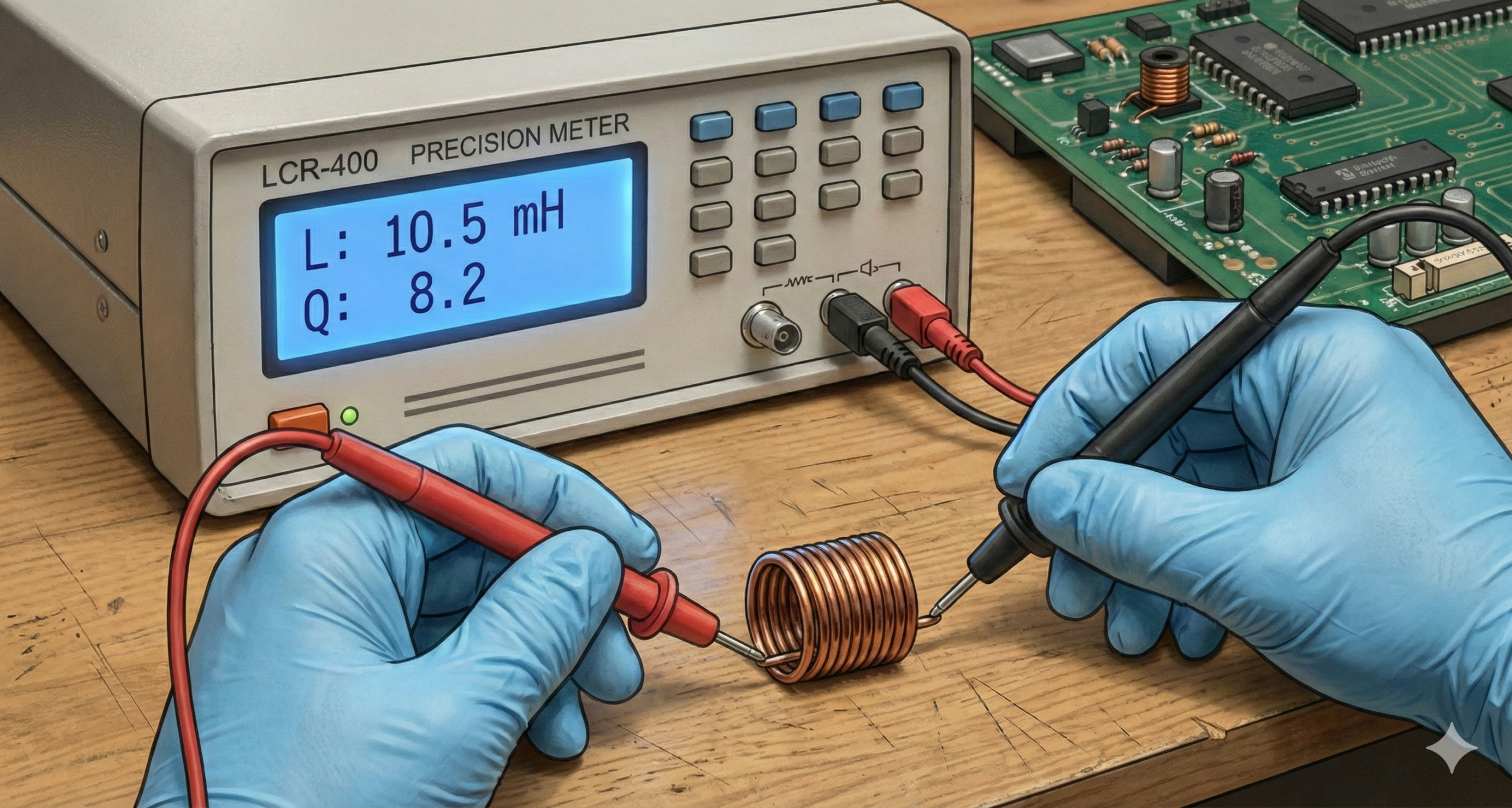
Method 2: Measuring Inductance with an Oscilloscope
If an LCR meter is unavailable, an oscilloscope and a function generator can be used to calculate inductance through circuit behavior.
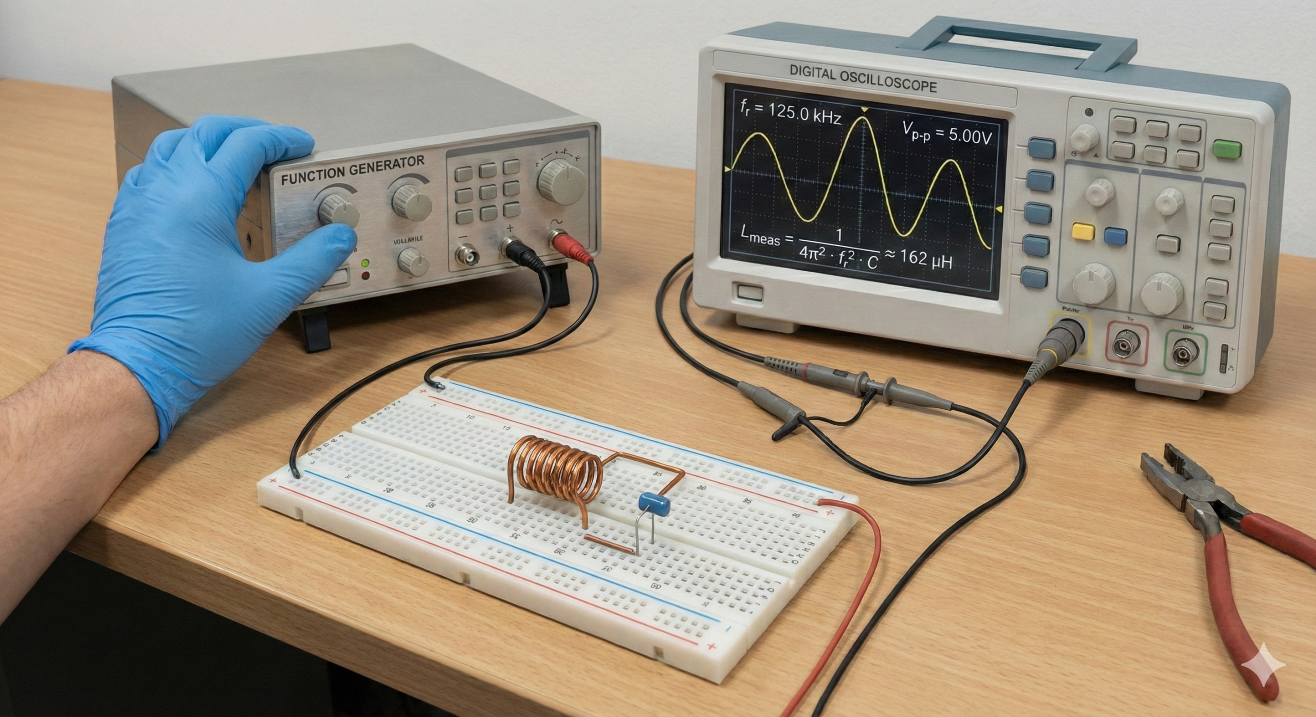
- The Resonant Method:
- Build a Tank Circuit: Connect the inductor in parallel with a capacitor of a known, precise value.
- Find the Peak: Connect a signal generator to the circuit and sweep through frequency ranges. Monitor the voltage on the oscilloscope. The voltage will peak at the resonant frequency.
- Calculate: Use the resonant frequency formula to solve for inductance ($L$), where $f$ is the frequency and $C$ is the known capacitance:
$$L = \frac{1}{4\pi^2 f^2 C}$$
- The Time Constant Method:
- Pulse the Circuit: Connect the inductor in series with a known resistor ($R$) and apply a square wave pulse.
- Measure the Rise: Current in an inductor cannot rise instantly. Measure the time ($\tau$) it takes for the voltage across the resistor to reach approximately 63.2% of its maximum value.
- Calculate: Derive inductance using the time constant formula:
$$\tau = \frac{L}{R} \implies L = \tau \times R$$
Method 3: Testing for Saturation Current (Isat)
A common pitfall is assuming an inductor’s value is static. In reality, inductors with magnetic cores can “saturate.”
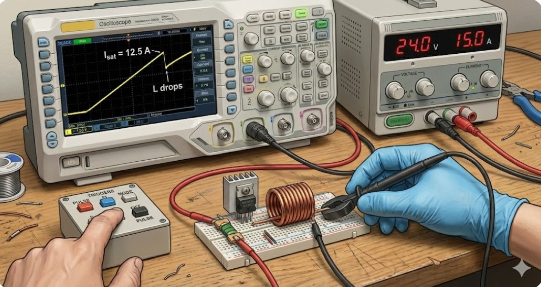
- Why Static Measurement Fails: Standard LCR meters use very small test signals. They cannot simulate the high currents found in power circuits. When an inductor saturates, its magnetic core reaches capacity, and its inductance drops rapidly—often turning the component into little more than a resistor.
- The Pulse Test: By applying a voltage pulse and monitoring the current with an oscilloscope, you can observe the current ramp. As long as the slope is linear, the inductance is stable. If the slope suddenly spikes upward (resembling a hockey stick), the core has saturated.
- DC Bias Adapters: Advanced testing involves injecting a steady DC current (DC Bias) into the inductor while measuring inductance. This allows engineers to plot an L vs. I curve, identifying exactly at what current level the inductance falls below an acceptable threshold.
Common Measurement Errors to Avoid
- In-Circuit Testing: Never measure an inductor while it is soldered into a complex circuit. Parallel capacitors or resistors will alter the impedance reading, leading to false data. Always isolate the component.
- Frequency Mismatch: Measuring an audio choke at RF frequencies (or vice versa) will result in inaccurate impedance values due to the frequency-dependent properties of core materials.
- Lead Inductance: When measuring very small coils (in the nanohenry/nH range), the test leads themselves may possess more inductance than the component. Use short, stiff leads or specialized surface-mount tweezers to minimize this error.
Summary of Tools
| Tool | Primary Use |
| Multimeter | Pass/Fail Check: Useful only for checking continuity (broken wires) and DC resistance. |
| LCR Meter | Precision Measurement: The standard for determining inductance values and efficiency (Q-Factor). |
| Oscilloscope | Advanced Analysis: Required for calculating inductance via resonance and testing for core saturation limits. |