Bipolar Junction Transistors (BJTs) function as the fundamental building blocks of modern electronics, acting primarily as current-controlled switches or amplifiers within a circuit.1 Due to their operational role in managing current flow, these semiconductors are susceptible to thermal runaway and voltage spikes, which often lead to component failure.2 Diagnosing a faulty transistor is a critical skill in electronics maintenance, as a single compromised component can render an entire printed circuit board (PCB) non-functional. While advanced oscilloscopes provide detailed waveform analysis, a standard digital multimeter offers a reliable and accessible method for verifying the structural integrity of the internal P-N junctions. This procedure relies on the principle that a functional BJT behaves electrically like two diodes connected back-to-back.
Tools and Prerequisites
Digital Multimeter |
|
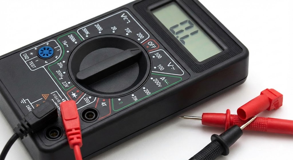 |
Ensure the device possesses a dedicated Diode Test function, which provides the necessary forward bias voltage to open the semiconductor junctions.
|
The Transistor and Test Probes |
|
| This guide focuses on Bipolar Junction Transistors (BJT), specifically NPN and PNP variants (e.g., 2N2222, BC547). Standard needle-tip probes are recommended for ensuring secure contact with small transistor legs.
|
|
Datasheet |
|
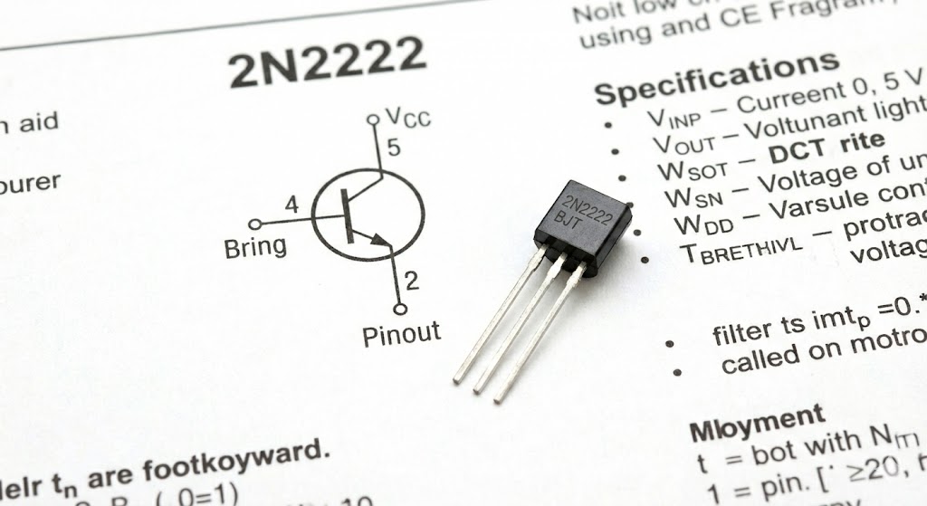 |
A technical reference sheet is required to accurately identify the pinout configuration (Emitter, Base, Collector) if it is not printed on the component.
|
Identifying Transistor Terminals and Type
Before initiating the electrical test, it is imperative to determine the physical pin layout and the polarity type of the component. Transistors are categorized into two primary polarities: NPN (Negative-Positive-Negative) and PNP (Positive-Negative-Positive). The testing methodology differs for each because the direction of the conventional current flow required to bias the junctions is reversed. While many plastic-cased transistors (such as the TO-92 package) follow a standard pinout, variations exist among manufacturers. Therefore, referencing the manufacturer’s datasheet is the most reliable method to distinguish the Base ($B$), Collector ($C$), and Emitter ($E$) terminals. Incorrect identification will lead to false negatives during the diagnostic process.
![]()
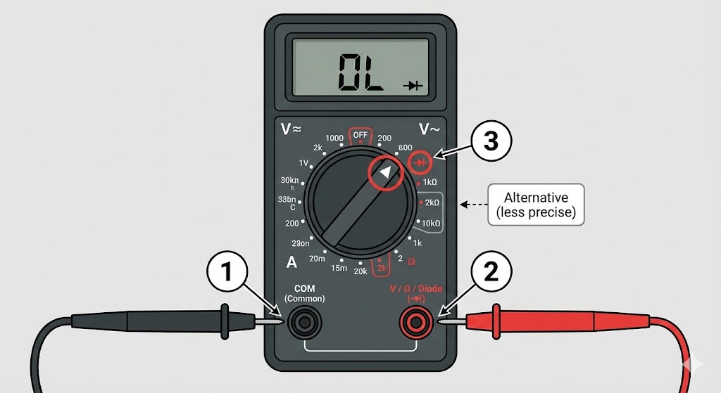
Setting Up the Multimeter
To accurately measure the potential barrier of the transistor’s internal junctions, the multimeter must be configured to inject a small current into the device.
- Insert the black probe into the port labeled COM (Common).
- Insert the red probe into the port marked for Voltage, Resistance, or the Diode symbol ($\Omega / V / \rightarrow+$).
- Rotate the central dial to the Diode Test Mode. This is typically represented by a small arrow symbol with a vertical line. If this mode is unavailable, the resistance setting ($2k\Omega$ range) may serve as a secondary alternative, though it is less precise for this specific application.
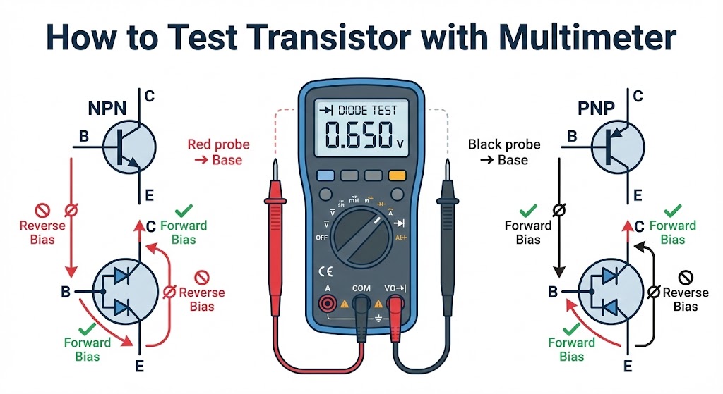
How to Test an NPN Transistor
An NPN transistor requires a positive voltage at the Base relative to the Emitter and Collector to allow current flow. Structurally, this can be visualized as two diodes with their anodes connected at the Base. The test involves verifying that the P-N junctions conduct current in the forward direction (Base to Emitter/Collector) and block it in the reverse direction.
- Connect the Red (Positive) probe to the Base terminal of the transistor.
- Touch the Black (Negative) probe to the Emitter terminal. Observe the multimeter screen; a functional silicon transistor should display a voltage drop between 0.6V and 0.7V.5
- Move the Black probe to the Collector terminal while keeping the Red probe on the Base. The reading should again be between 0.6V and 0.7V.
- Reverse the probes: Place the Black probe on the Base and the Red probe on the Emitter and Collector sequentially. The meter should display “OL” (Over Limit) or “1”, indicating no current flow (infinite resistance).
![]()
How to Test a PNP Transistor
The PNP transistor operates on the inverse principle of the NPN variant.6 In this configuration, the Base consists of N-type material, meaning it must be at a lower potential than the Emitter or Collector to conduct. Consequently, the polarity of the test probes must be swapped to forward-bias the junctions correctly.
- Connect the Black (Negative) probe to the Base terminal.
- Touch the Red (Positive) probe to the Emitter terminal. Note the voltage drop reading, which should typically range from 0.6V to 0.7V.
- Touch the Red probe to the Collector terminal. A similar voltage drop should be observed.
- Reverse the probes: Place the Red probe on the Base and the Black probe on the Emitter and Collector. The multimeter should indicate an open circuit, displayed as “OL”, confirming that the junctions are blocking reverse current effectively.
![]()
Interpreting the Results (Good vs. Bad)
The following table summarizes how to interpret the numerical values displayed on your multimeter to determine the health of the component.
| Condition | Multimeter Reading | Conclusion |
| Forward Bias | 0.5V – 0.9V | Functional Junction (Silicon) |
| Forward Bias | 0.2V – 0.3V | Functional Junction (Germanium) |
| Continuity / Beep | 0.00V or near zero | Shorted (Defective) |
| Reverse Bias | “OL” or “1” | Good Isolation (Normal) |
| Both Directions | “OL” (No reading) | Open Circuit (Defective) |
Common Transistor Faults
Transistors generally fail due to excessive heat dissipation or voltage overloads that physically damage the internal semiconductor lattice.7 This damage manifests in two distinct electrical states, both of which render the component unusable.
- Shorted Transistor: This occurs when the internal barrier between the P and N layers breaks down completely. Current flows freely in both directions (like a simple wire), resulting in a near-zero voltage reading ($< 0.05V$) and often a continuous beep from the multimeter.
- Open Transistor: This failure mode mimics a severed wire. The internal connection is physically broken, preventing current flow regardless of probe polarity. The multimeter will display “OL” in both forward and reverse bias tests.
![]()