
In the world of electronics, where integrated circuits and flashy processors often steal the spotlight, there exists a humble yet indispensable component that works silently behind the scenes: the inductor. Alongside resistors and capacitors, inductors complete the trio of fundamental passive components that form the backbone of virtually every electronic circuit ever created. These components are termed “passive” because they do not require an external power source to operate and cannot amplify a circuit’s power; instead, they manage energy in their own unique ways. While resistors dissipate energy as heat and capacitors store energy in an electric field, inductors specialize in storing energy in a magnetic field.
Inductors, often unrecognized, are the unsung heroes within many devices we use daily. From the power supply that charges your laptop to the radio receiver in your smartphone, inductors play multiple critical roles. They are masters of current control, adept at filtering out unwanted electrical noise, efficiently transferring energy between circuits, and precisely tuning frequencies in communication devices. Despite their simple appearance—typically just a coil of wire—their impact on the stability, efficiency, and functionality of modern electronics is profound.
- Key Quick Facts:
- Along with resistors and capacitors, inductors are one of the three fundamental passive circuit elements.
- They store energy in a magnetic field, unlike capacitors, which store energy in an electric field.
- They are also known as coils, chokes, or reactors, depending on their specific application.
- The basic unit of inductance is the henry (H), named after scientist Joseph Henry.
- They fundamentally oppose any change in the current flowing through them.
Definition: What Exactly Is an Inductor?
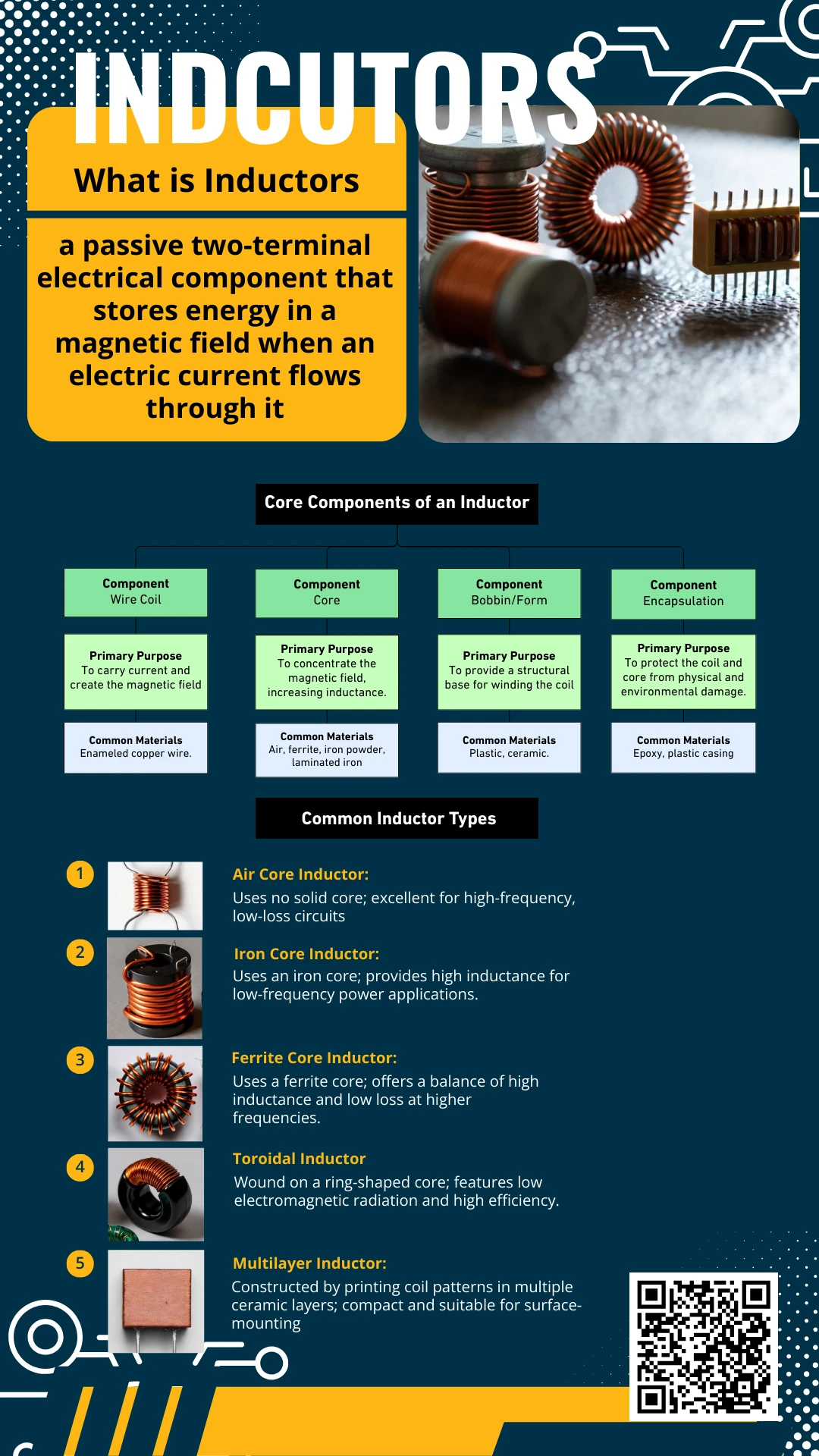
An inductor can be formally defined as a passive two-terminal electrical component that stores energy in a magnetic field when an electric current flows through it. This property, known as inductance, is a direct consequence of the laws of electromagnetic induction discovered by scientist Michael Faraday, whose pioneering work in the 19th century laid the foundation for this critical component. At its heart, an inductor is a simple entity. It typically consists of a length of conductive wire, most often made of copper, wound into a coil around a central core. This coiled structure is the key to its function, as it concentrates the magnetic field created by the current flowing through the wire, thereby enhancing its inductance.
The core idea behind an inductor’s operation is its ability to resist changes in current. Imagine an inductor as the electrical equivalent of inertia in mechanics. Just as a heavy object resists changes to its speed, an inductor resists changes to the flow of current passing through it. When the current attempts to increase, the inductor absorbs energy, creating a magnetic field. When the current attempts to decrease, the inductor releases that stored energy back into the circuit to maintain the current flow. This fundamental behavior makes it an invaluable component for managing current flow and energy in dynamic electrical systems.
- Core Concept in a Nutshell:
- Energy Storage:Acts as a tiny reservoir, but for magnetic energy rather than electrical charge.
- Current Stabilizer:Smooths out fluctuations in current, preventing sudden spikes or drops.
- Frequency-Dependent Resistor:In AC circuits, it resists current flow in a way that depends on the signal’s frequency.
How an Inductor Works (Simple Explanation)
The operation of an inductor is elegantly explained by Faraday’s law of electromagnetic induction and Lenz’s law. When an electrical current first starts to flow through the coiled wire of an inductor, it generates a magnetic field around it. As this current—and consequently the magnetic field—changes, it induces a voltage within the coil itself. This self-induced voltage is often called a back electromotive force (back EMF). Crucially, Lenz’s law dictates that the polarity of this induced voltage is always in a direction that opposes the change in current that created it. This is the fundamental “inertial” property of the inductor.
This opposing reaction is a continuous process. If the current through the inductor tries to increase, the induced voltage slows down the increase. If the current tries to decrease, the induced voltage acts to keep it flowing. It is vital to understand that this opposition applies only to changes in current. When a steady, constant direct current (DC) flows through an ideal inductor, the magnetic field remains stable, no back EMF is generated, and the inductor behaves like an ordinary piece of wire, offering no resistance. The real magic happens with alternating current (AC) or in circuits where the current is constantly switching, as the inductor is perpetually acting to smooth out these variations.
- Steps of Inductance Creation:
- Current Flow:An changing electric current begins to flow through the wire coil.
- Magnetic Field Generation:The current produces a expanding magnetic field around the coil.
- Back EMF Induction:The changing magnetic field induces a voltage (back EMF) in the coil itself.
- Opposition:The induced voltage has a polarity that opposes the initial change in current, in accordance with Lenz’s law.
Core Components of an Inductor
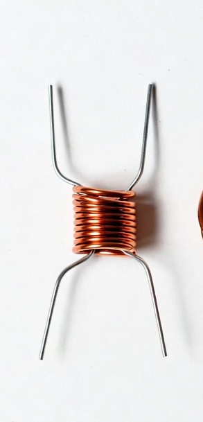
The physical construction of an inductor is straightforward, yet each element is carefully chosen to achieve specific performance characteristics. The primary component is the wire coil itself. The number of turns, the diameter of the wire, and the tightness of the winding all directly influence the inductor’s final properties. For instance, a coil with more turns will have a higher inductance because the magnetic field from each turn links with the others, reinforcing the overall field strength. The wire is typically insulated with a thin enamel coating to prevent short circuits between adjacent turns.
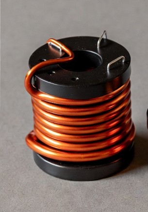
The second critical component is the core around which the coil is wound. The core’s primary function is to increase the inductance by concentrating and strengthening the magnetic flux lines. A core provides a more easily magnetizable path for the magnetic field than air, significantly boosting the inductor’s efficiency and allowing for a smaller physical size for a given inductance value. Cores are made from various materials, each chosen for its specific magnetic properties, such as permeability, and its suitability for different frequency ranges and power levels.
Table: Core Components of an Inductor
| Component | Primary Purpose | Common Materials |
| Wire Coil | To carry current and create the magnetic field. | Enameled copper wire. |
| Core | To concentrate the magnetic field, increasing inductance. | Air, ferrite, iron powder, laminated iron. |
| Bobbin/Form | To provide a structural base for winding the coil. | Plastic, ceramic. |
| Encapsulation | To protect the coil and core from physical and environmental damage. | Epoxy, plastic casing. |
Types of Inductors
To suit a vast array of applications, inductors are manufactured in various forms and types. The core material is one of the most significant differentiators, as it defines the inductor’s operating frequency, power handling capability, and overall efficiency. Air core inductors, as the name implies, have no solid magnetic core. The coil is wound on a non-magnetic former or is self-supporting. The absence of a solid core eliminates core losses, making these inductors ideal for very high-frequency applications like radio transmitters and tuning circuits, where minimizing signal loss is critical.
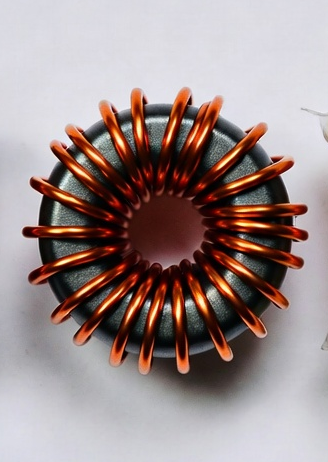
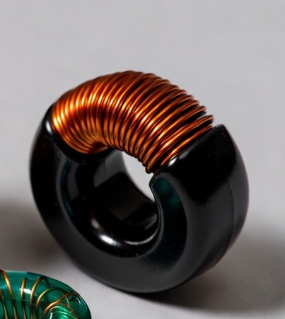
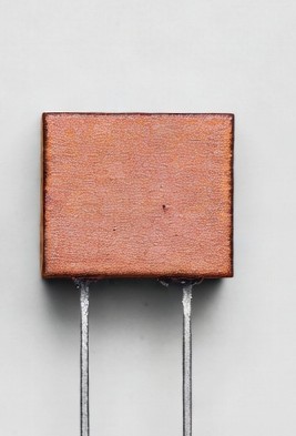
Conversely, iron core inductors and ferrite core inductors use solid magnetic materials to achieve high inductance values in compact sizes. Iron cores, often laminated to reduce energy losses from eddy currents, are excellent for low-frequency power applications, including audio equipment and AC power line filtering. Ferrite, a ceramic ferrimagnetic material, is widely used for intermediate and high-frequency inductors because it has high electrical resistance, which prevents eddy currents. You will find ferrite cores in switch-mode power supplies and radio-frequency interference (RFI) chokes. Other common types include toroidal inductors, which have a donut-shaped core that confines the magnetic field almost entirely within itself, minimizing electromagnetic interference (EMI) with nearby components. Multilayer inductors are a modern, compact type where the coil is fabricated as a layered pattern inside a ceramic body, making them perfect for densely packed surface-mount technology (SMT) boards in smartphones and other portable devices.
- Common Inductor Types:
- Air Core Inductor:Uses no solid core; excellent for high-frequency, low-loss circuits.
-
- Iron Core Inductor:Uses an iron core; provides high inductance for low-frequency power applications.
-
- Ferrite Core Inductor:Uses a ferrite core; offers a balance of high inductance and low loss at higher frequencies.
-
- Toroidal Inductor:Wound on a ring-shaped core; features low electromagnetic radiation and high efficiency.
-
- Multilayer Inductor:Constructed by printing coil patterns in multiple ceramic layers; compact and suitable for surface-mounting.
The existence of such a diverse range of inductor types stems from the need to optimize performance for specific applications. There is no universal “best” inductor. An engineer will select an air core for a sensitive radio receiver, a ferrite core for a power supply, and a multilayer chip inductor for a mobile phone, demonstrating how form and function are tailored to meet the demands of the circuit.
Key Electrical Properties of an Inductor
Selecting the right inductor for a circuit requires a deep understanding of its key electrical properties. The most fundamental of these is Inductance (L). Measured in henries (H), inductance is the quantitative measure of an inductor’s ability to store magnetic energy and oppose changes in current. It is the core specification of the component, with practical values ranging from nanohenries (nH) for high-frequency circuits to several henries for low-frequency power chokes. Another critical property is Reactance (X_L), which is the effective resistance an inductor presents to an alternating current (AC). Unlike regular resistance, reactance is frequency-dependent and increases with both frequency and inductance, following the formula XL=2πfLXL=2πfL .
The Quality Factor (Q-factor) is a dimensionless parameter that describes how “ideal” an inductor is. It is defined as the ratio of its reactance to its effective resistance at a given frequency. A high Q-factor indicates low energy loss and a sharp resonance peak, which is crucial for selective tuning circuits in radios. Furthermore, every physical inductor has a Saturation Current (I_sat), which is the direct current (DC) level at which the core can no longer store additional magnetic energy. Exceeding this current causes a sharp drop in inductance, leading to circuit inefficiency and potential failure. Engineers must also consider DC Resistance (DCR), the inherent resistance of the wire, which causes power loss as heat, and the Self-Resonant Frequency (SRF), the frequency at which the inductor’s inter-winding capacitance resonates with its inductance, beyond which it ceases to behave as an inductor.
Table: Key Electrical Properties
| Property | Meaning | Impact on Circuit |
| Inductance (L) | Ability to store magnetic energy and oppose current change. | Determines the core energy storage and filtering capability. |
| Reactance (X_L) | Frequency-dependent opposition to AC current. | Determines how much the inductor impedes AC signals of different frequencies. |
| Q-Factor | Measure of efficiency (reactance to resistance ratio) . | Higher Q means sharper filters and lower energy loss. |
| Saturation Current | Current at which the core magnetically saturates. | Limits the maximum current before inductance plummets. |
| DC Resistance (DCR) | Inherent wire resistance to DC current. | Causes power loss and heat generation. |
| Self-Resonant Frequency | Frequency where parasitic capacitance resonates with L. | Defines the upper frequency limit for proper inductive behavior. |
How Inductors Are Used in Electronics
The unique properties of inductors make them versatile components with a broad spectrum of applications across the field of electronics. One of their most common uses is in power supply filtering. In both traditional linear supplies and modern switch-mode power supplies (SMPS), inductors work with capacitors to smooth out pulsating DC, reducing the “ripple” voltage and creating a clean, stable output voltage essential for sensitive digital circuits. They are equally vital in radio frequency (RF) circuits, where they are used in LC tank circuits (combined with capacitors) to select or “tune in” to specific frequencies, as seen in the front ends of radios, televisions, and wireless communication modules.
Furthermore, inductors serve as fundamental energy storage devices in power converters, temporarily holding energy in their magnetic field before releasing it to the load at a different voltage, which is a key principle behind buck and boost converters. When used as chokes, inductors exploit their frequency-dependent reactance to block high-frequency AC noise while allowing DC or low-frequency signals to pass unimpeded, protecting equipment from interference. When two or more inductors are placed in close proximity to share a magnetic field, they form a transformer, enabling the efficient stepping up or stepping down of AC voltages for power transmission and voltage adaptation in power adapters. Other notable applications include their use in sensors for detecting metal objects or position, and in audio equipment for cross-over networks that direct appropriate frequencies to different speakers.
- Primary Applications:
- Power Supply Filtering:Smoothing rectified AC to create stable DC.
- RF Tuning Circuits:Selecting specific frequencies in radios and transceivers.
- Energy Storage:Temporarily storing energy in switch-mode power converters.
- Chokes:Blocking high-frequency AC noise in power and signal lines.
- Transformers:Coupling circuits to transfer power and change voltage levels.
In the real world, these applications translate directly to the devices around us. The charging brick for your laptop uses inductors in its power conversion and filtering stages. A traffic light uses an inductive loop buried in the road to detect waiting vehicles. The wireless charging pad for your smartphone uses a large inductor to create an oscillating magnetic field that transfers energy to a second coil inside your phone.
Advantages and Limitations of Inductors
Inductors offer several distinct advantages that make them irreplaceable in circuit design. Their primary strength is their ability to handle high currents, particularly power inductors with thick wire windings, which makes them robust components in power electronics. They are also highly effective for filtering and noise suppression, especially in power lines, where they can choke out high-frequency noise that capacitors might struggle with. Furthermore, when used in resonant LC circuits, high-Q inductors provide excellent frequency selectivity, allowing for the precise tuning required in communication systems. Finally, their fundamental property of resisting current change provides the critical benefit of protecting circuits from current spikes, preventing potential damage to sensitive components.
However, inductors are not without their limitations. One of the most significant challenges is their physical size and weight; high-inductance values often require large cores and many turns of wire, making them bulkier and heavier than comparable capacitors and resistors, which can be a constraint in miniaturized devices. Unlike ideal components, real-world inductors have parasitic effects, including inherent resistance (DCR) that causes power loss as heat and inter-winding capacitance that limits high-frequency performance. They are also more complex to manufacture than other passive components, leading to a generally higher cost. Moreover, their magnetic fields are not always contained; they can radiate electromagnetic interference (EMI), which can disrupt the operation of nearby circuits, requiring careful shielding in sensitive designs.
- Advantages:
- Robust current-handling capability.
- Effective noise suppression and filtering in power lines.
- High frequency selectivity in tuning circuits.
- Inherent protection against current spikes.
- Limitations:
- Relatively large physical size and weight for given values.
- Parasitic resistance and capacitance lead to energy losses and frequency limitations.
- Generally more expensive and complex to fabricate than resistors or capacitors.
- Stray magnetic fields can cause electromagnetic interference (EMI).
In practical circuit design, engineers must carefully weigh these advantages and limitations. The decision to use an inductor involves a trade-off between its unique performance benefits and the associated costs in space, power loss, and potential noise. Understanding these constraints is essential for optimizing circuit performance and reliability.
Inductor vs. Capacitor: Quick Comparison
Inductors and capacitors are both energy-storage components, but they perform complementary roles in electronic circuits. Understanding their differences is key to knowing when to deploy each one. Fundamentally, an inductor stores energy in a magnetic field created by a current, while a capacitor stores energy in an electric field created by a voltage potential across its plates. This core distinction leads to opposite behavior in circuits: an inductor opposes changes in current, whereas a capacitor opposes changes in voltage.
Their frequency response is also a study in opposites. In AC circuits, an inductor’s reactance increases with frequency (XL=2πfLXL=2πfL), meaning it blocks high frequencies and passes low frequencies. A capacitor does the exact opposite; its reactance decreases with frequency (XC=1/(2πfC)XC=1/(2πfC)), allowing it to pass high frequencies while blocking low frequencies and DC . From a DC perspective, a steady-state inductor acts like a short circuit, while a capacitor acts like an open circuit. When considering ideal components, inductors dissipate no power, but real capacitors also have lower equivalent series resistance (ESR) and are generally more efficient at high frequencies than real inductors, which have resistive losses in their wire.
Table: Inductor vs. Capacitor
| Factor | Inductor | Capacitor |
| Energy Storage | In a magnetic field. | In an electric field. |
| Opposes Change In… | Current. | Voltage. |
| Frequency Response | Reactance increases with frequency; blocks AC and passes DC. | Reactance decreases with frequency; passes AC and blocks DC. |
| DC Steady-State | Acts as a short circuit. | Acts as an open circuit. |
| Common Applications | Chokes, RF tuning, power filtering, energy storage in converters. | Coupling, bypassing, timing circuits, energy storage, AC filtering. |
- When to Choose Which:
- Use an inductorwhen you need to smooth current, filter out very high-frequency noise (choke), or store energy for power conversion in a way that handles high currents well.
- Use a capacitorwhen you need to smooth voltage, filter out low-frequency noise, couple AC signals while blocking DC, or create timing delays.
Real-Life Examples of Inductors You Use Every Day
Inductors are deeply embedded in the fabric of modern technology, and you interact with devices containing them on a daily basis, often without realizing it. One of the most ubiquitous examples is the power adapter for laptops and other electronics. Inside these “power bricks,” inductors are crucial components of switch-mode power supplies, where they help efficiently convert the AC wall voltage to the low-voltage DC required by your device while minimizing energy loss. Similarly, if you use a wireless smartphone charger, you are directly leveraging the principle of mutual inductance between two coils—one in the charging pad and one in your phone—to transfer energy without any physical connection.
In the realm of communication, smartphones and Wi-Fi routers are packed with tiny inductors. They are integral to the radio frequency (RF) circuits that filter and tune into the specific frequencies used for cellular data, Bluetooth, and wireless networking, ensuring a clear and stable connection. On a larger scale, electric vehicles (EVs) rely heavily on high-power inductors within their power electronics to manage the flow of energy between the battery and the motor, enabling rapid charging and efficient driving. Even a humble car key can contain an inductor; passive entry systems use an inductive sensor in the car to detect the small coil in the key fob, allowing for keyless ignition.
- Everyday Devices:
- Power Adapters:Use inductors to convert and smooth AC to DC.
- Wireless Chargers:Employ paired inductors to transfer power wirelessly.
- Smartphones/Routers:Contain miniature inductors for RF tuning and signal filtering.
- Electric Vehicles:Utilize large inductors in power converters and motor drives.
- Induction Cooktops:Use a powerful inductor to generate heat directly in cookware.
These examples matter because they illustrate how this fundamental component, discovered in the 19th century, remains absolutely vital to the functionality, efficiency, and convenience of 21st-century technology. Inductors enable the miniaturization, power efficiency, and wireless capabilities that define our modern electronic landscape.
Conclusion
The inductor, a simple coil of wire, is a cornerstone of electrical engineering whose importance cannot be overstated. From its foundational principle of resisting changes in current, it derives a remarkable range of applications, including energy storage, frequency filtering, and power conversion. While often hidden from view, its role is critical in ensuring the stable, efficient, and reliable operation of countless electronic devices, from the most basic power supply to the most advanced communication system.